ZBrushCentral

Questions and Troubleshooting for Displacement Exporter

Hi guys…I’m following the multidisplace workflow. Just like that KTaylor does.

But say I want to work with 32 float maps…
I sculpt the head part of my model with a buffer zone for the neck…
Now I want to continue painting, this time on the neck part with a buffer zone for the head, right?
I want to apply a displace on the mesh to continue the pattern I was painting.
So I import the disp map I previously baked, but ZB prompts this message:
Immagine.JPG

To generate the map with DExporter I used the Maya quick code
DE-LBEK-EAEAEA-32MAYA-AD

I tried with other different configurations… same error message.

Another thing…is it possible to re-apply in ZB the 32 bit disp maps on a tool with multiple UVs?
If yes, how do I use the AD Factor? I mean, if I want to re-apply the disp on the mesh in order to continue painting the pattern, I need a displacement at the very same height of the previous map, so I have to input a specific AD Factor.
How shall I do it practically? Does it work on 32 bit maps also?
If yes, I have this error during image importation!!

Fretwizard asked me this on another thread and I though it should be over here as well so

{Fretwizard } KTaylor, I read you tutorial on multiple displace fix, is it made on a single UV map? If not, how did you reapply the previously painted maps on the buffer zones of your next-to-paint portion of the model since it’s multiple UVs?
It seems that you can only generate multiple disp map (and not texture maps)
and you can’t apply multiple disp map or text map. Am I wrong?

[Ktaylor]

No that is a good question and its basically one of those things where you are jumping through hoops to make it work ( I really hope Zbrush 2.5 can handle as many polys as they say it can so we dont have to cut our tools up into multiple tools anymore!!)

Okay so to answer your first question, yes all my UV’s are in Different UV Zones, and yes that does pose a problem in Zbrush becuase you can only assign one map to a Z tool so here is the work around for this, man its almost not worth it!! ahaha

Lets say you have a Hand that is UV’ed from 0-1 like normal, then the foreArm is UVed from 0-2 so its in the next uv range over right next to the hand, so if you use the Group UV feature it will create polygroups on Zbrush and you can now pick the hand and the forearm really easy and these match up with your UV zones that in turn matches up with the textures that will be created so everything is nice and clean and managable.

so now you want to refine the hand, so you hide everything but the hand and the first row or so of polys from the forearm mask it all and delete hidden (ps I think you need to mask it at the highest level of detail to preseve that detail when you “delete hidden”)

Now you can save this as a new Ztool like Hand.ztl, so you load that up and now you are ready to divide the hand more and continue detailing so you do so and you detail right across that seam at the wrist that goes into the next tool, the forearm, you can select the frame feature at the top and see where that seam is really easily, so you are done and now you want to get that detail that is on the first couple of rows of the forearm over to your other Ztool that is the forearm, and probobly a couple rows of the hand, and the bicept right, right.

so with your Hand tool still loaded go ahead and use the multidisplace plug to make your displacement maps, they are saved of as world scale and ready to be used in your final software renders, so you have the hand Dis map which is good to go and you have a partial map for the forearm that has that detail that goes right across that seam DONT DELETE THIS AS YOU WILL NEED IT LATER!!!

so that we stay clear we will call this Displacement map for the Hand, Map A

Map A= realworld scale Dismap for hand
Map B= realworld scale Dismap for partial forearm

now at this point hide the hand so that you are only seeing the partial tool for the forearm, now using the Tool/Displacement feature create a displacement map for this partial area, so that DisMap goes up to the alpha pallate with the Alpha Depth factor , save this Map out and note the alpha depth factor
this map is

Map C= Alpha Depth factor, partial wrist map.

So now load up your tool for the forearm, Hide the buffer zones for the wrist and Bicept area, load up Map C into the alpha pallete so it is selected, go to the displacement tool and select, mode/displacement, enter in the alpha depth number you got when you made Map C into the intensity field, now hit apply displacement you should get all that detail around the seam now,

( you need to have this tool divided as many times as your hand tool or there may not be enough polys to recreate the detail from the displacment map, you apply Map C as a displacement at this tools new highest level)

so now you can continue sculpting the fore arm with the detail provided at the seam, will notice however that some artifacts may appear at the boarders of the tool, just sculpt those out and continue to detial, so now you are done and you run the multidisplace and you get your full forearm displacement map, and partial hand, and bicep
the new full displacement map that is the fore arm is now

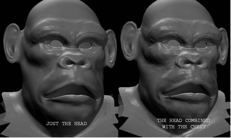
Map D= Full fore arm world scale displacement, so you what you want to do is becuase of the potential edge artifacts that could now cause a seam between Map_D and Map_A ( the final forearm and hand .tiffs, is load up Map_D and Map_B into photoshop (turn colormanagement off before you do this) and combine the original seam detail with the final sculpted detail ( put Map_B on a layer and Map_D above it and just erase the seam area of Map_D so that you get the original seam area of Map_B

now you should have a new map for the forearm that you can save out and it will be seamless with your hand displacement map,

I know this is a lot of crap but I cant find an easier way to do , hopefully someone else can!!! or even better with 2.5 we wont have to cut up the mesh cause we can have 20 million polys per tool!!

hope this makes sense let me know if it doesnt

Thanks Thanks and thanks again KTaylor!!!

I finally can see the light!!! :eek: :eek: :smiley:

However…I suppose that after you delete the hidden parts of the tool the Morph target gets lost, doesn’t it? So you generate the map with a smoothed mesh?

I wrote about some error messages during the image import.
Now. after I read that, as you say, you must generate an ordinary 16 bit map to re-apply the details…well, then is that error message normal?

I wrote also that I was able to make multiple UVs with AUVTiles.
I WAS in part WRONG because they make seams artifacts all the times. Maybe that’s because there’s a UV patch for every poligon while in the hand-made UVs you have 1 unique patch for part.
So if I have to make only one patch per part, then I’m obliged to make a UV layout for every part I wasn’t able to keep together once stretched the UVs.

What a pain in the…:mad:

you mean like when you first bring your mesh in you store a morph target so you can switch back to before you make your dis maps?

if so then yeah that gets nuked but I dont use that anyways, I always generate my displacements from level 2 ( I make sure and bring a pretty lean mesh of just what I need for l1) that way any changes I make during sculpting are well represented in teh L2 geometry, and you can be guaranteed to have an all Quad mesh :slight_smile: hope that clears some of that up

I understand :+1:

I tried to work your way. I suddenly discovered that LightWave cannot handle 32 float images.

If I set the DE options for a 1 channel 16 bit image, does the multidisplace calculate the displacement by world coordinates anyway? With which settings?
If yes, I could do the Photoshop work without changing the bits (which will cause a big loss of detail, I presume, and a lot of artifacts).

Fretwizard

Im not sure what it calculates with those settings, Scott do you know??

Yeah, Multidisplace2 will calculate realworld scale into a 32bit map for the original imported object scale. 16 bit wont have scale baked in if the model started outside ZBrush and was imported in so you will need to adjust your gain for those maps.
With 32bit the scale is part of the map itself letting you use a consistent scale factor between all your displacements.
Setting to one channel will create a grayscale map and altering it in photoshop will cause some serious artifacts down the line. Try 3 channel 16 bit (provided LW does use RGB for displacement) You can also rescale your object to the ZBrush scale by checking the obj file you export from ZBrush. The rescale factor is at the top of the file when opened in a text editor (#Auto Scale)
This should help keep your maps consistent if there is no other option.

S

LW does support 32 bit float images. It was the first program to support the HDR format Paul Debevec did all his work with back in the late 90’s, i believe its natively supported the OpenEXR format for abit alos which i think is 40 or 48 bits log. LW however may not support the particualr file format… flavour of Tif… bits per channel your trying to import. Lynx3d created a plugin called normal displacer to handle 16 bit grayscale… and im told float displacement maps too. Look for Lynx3d’s website, and the Normal displacment plugin he wrote, it works far better than the native way LW handles displacement maps. Try adding a second F to your file extension like .tiff instead of .tif -Hope you make some headway -Ken

Jusy now I figured out that, in LightWave, 32 bit world scale displacement maps are useless.
Because in the Normal Displacement plugin the only settings are: Displacement amount (in meters) and the “Luminance Center” setting, in which you choose the grey level (from 0% to 100% in the grey scale) to consider as no-displacement-area. So if I anyway succeed in importing some 32 bit images, I wont be able to figure out the mid point of that map.
That’s not like Maya, where you use the alpha gain and alpha offset. When I tried to import one of those images, LightWave recognises the float 32 format, but it cannot use it and prompts an error, EVEN if it supports the HDR and the OpenEXR

I KNOW the 16tiff image loader, from lynx3D, I was using right now to load the standard 16bit Zbrush maps.

Besides the bits stuff, I did some tries with 16 bit maps, by Kris’ workflow, I edited them in photoshop to remove the artifacts from the re-application of the displacement in ZB, and NO ARTIFACTS OCCURED!
So I think I’ll continue the way KTaylor did, but using 16 bit maps, with the same trick he used, that one of creating a poligon aside the mesh, with the maximum and minimum displacement painted on it.

Thanx everyone for the precius info…

Your luminance center should be 50% gray since the maps are output from ZBrush as such. Otherwise I dont really know much about Lightwave.

Above I meant to say altering 32 bit and 16 bit will cause artifacts. I dont know about 16 bit single channel though. I havent had a chance to watch the video yet (super busy but I want to) so I dont know what the process is for removing artifacts in PS but it sounds really cool!

edit
OOPS I thought you meant Kris’s video not K taylor… So many Kris’s : P
I see the photoshop technique you mean… awesome cool info : D
true, if you have color managment off you should be fine just dont auto level or alter the map balance itself. I also think if you save 32bit maps in Photoshop it alters the file.

KTaylor, didnt you find resaving a float map in Photoshop makes it into 16 bit?

end Edit

S

I have been using the 32 bit float with the displace exporter while cutting up my mesh and creating multiple disp maps. And I have been getting OK results when rendering out individual parts of my mesh, but when I start to combine everything together I get a different result. I’m following Ktaylor’s approach to seamless multi displacement and everything works fine but the mesh seems to get muttled and displaces slightly in unwanted places as seen in the attached images. It looks almost as though in the second version that the mesh is not being subdivided enough because I can see what looks like triangles within the surface. Yet when I bump up the subivisions in the approximation editor in maya I get no change. Does anyone know why this is happening? Any help would be apreciated.

Jeff

Attachments

Zbrush_monkey.jpg

monkey displacement.jpg

Your luminance center should be 50% gray since the maps are output from ZBrush as such.

I know it man…but if I’d use some 32bit maps, their zero-displacement area IS NOT A 50% GREY ANYMORE, so I should try to figure out the right percent.
Why have I to suffer? :wink: Just keep using 16bit maps :slight_smile:

About Photoshop, that’s the workaround KTaylor posted in post 62…just EFFICIENT, it dealt with 32bit, but I got it work with 16bit also.

OOPS I thought you meant Kris’s video not K taylor… So many Kris’s

No…I meant KTaylor…why? Are there other Kris? WHAT’S THE VIDEO?

hahah no no, the texturing video on toppage. Watch it it rocks.

Why do you say 32bit maps no longer have 50% gray as no displacement??

Cool that you got it working in 16 bit : )

Scott

Perhaps Fretwizard this threadwill help you to understand how zbrush creates it’s displacement maps and where it’s values come from. I think this thread is a must read for anyone using displacements.

I compared the 16bit and 32bit maps. I saw that the 32bits had a base-grey that was lighter than the 16s ones. Then I suppose that, in an absolute grey scale, the right percentage that I needed to “center” the displacement was not 50% anymore. So I thought that if I didn’t want to waste time to tweak the values, I’d keep on using the 16s and keep on setting 50% Luminance Center.

Sure…If I had a displacement tool like Maya’s, then I would prefer the 32bit ones…It’s just a matter of "I only have that sort of tool in LW, I know how to work with it on 16s, so why to blast my mind about how to make the 32s work? :stuck_out_tongue: :smiley:

I could correct the seam artifact in PS as well, as KTaylor said. You just have to disable the color management, so PS does not change the color palette when saving the image.

Best Regards

Hey Scott, Yeah I found opening the 32 bit .tiff that Zbrush saves out in Photoshop and just saving it back it will reduce it to 16 bit.

Fretwizard -

How are you comparing grey-scale values of 16 bit and 32 bit? What program are you using? 32 bit files have been tested in production at major studioes and the base should be 50% grey no matter what the bit depth is.

If you are getting a different result at render time, I would really like to know the details of your process. :slight_smile:

If you are using Photoshop to view these it is worth bearing in mind that Photoshop doesn’t view 32 bit maps but it will open them and convert them to 16 bit as KTaylor mentions. :slight_smile:

Best,

Ryan

The devils in the details… the version of Photoshop your using is the key… Photoshop CS2 will work with 32 bpc (bits per channel)

Photoshop CS allows up to 16 bpc

And Photoshop 7, i wanna say will not let you work with a 16 bit grayscale image.

Also check your colour managment settings in the prefs od PS, it may be adjusting your grays etc without you even knowing… turn managment to off. -Ken

I use Photoshop CS2, I don’t have tools to compare the depth of the images.
If you disable the color management in PS, the image should be opened correctly, right?

So why the 32bits are brighter than 16 ones? I mean the ZERO-DISP GREY.

Anyway LightWave cannot load 32bits of that type, except for HDR an OpenEXR.
So I’ll use 16s.

Ryan, Follow the trick KTaylor said in post 62 of this thread.:+1: