That’s it, thank you so much.
Sorry for blowing up this topic, I feel like such a noob. I know it’s possible to create Multimeshes from Subtools but is it possible to create Subtools from Multimeshes to previous color for polypainting later?

Such a large number of superb meshes…
It would be great to have:
- A searchable data-base
- A visual catalog organized alphabetically
Searching through all the threads is a hit and miss situation, not to mention extremely time-intense
Using the search engine for the thread is pretty lame - typed in “buckle” = nothing, typed in “buckles” = only 2 hits
Currently looking for a simple adjustment buckle like those on the straps of coveralls that help adjust the length of a strap
The bigger the category gets, the harder it gets to find specific items
A catalog would be handy.Badking has one going on his site, but I can’t say how well the search function works and it probably isn’t as extensive (yet, it’s constantly growing!).
Otherwise I think you’re limited to using the search, or browsing the thread gallery to isolate attachments (http://www.zbrushcentral.com/zbc-thread-gallery.php?tid=170167).
Is it possible to get wrapmode to work with any of the IMM brushes? I’ve toggled it on but it doesn’t actually function :(? I just figured it would make creating tileable textures much easier.
Hello, I’m currently working on some Cactus for my personal project and i can’t figured it out how the IMM bounding box and axis is controlled by ZB to orient and aligned the Mesh onto the Surface.
Have a look at this:I’ ve made some different Pine element in Modo and loaded them inside Zbrush as different subtool.
So at this time the Pine element are just different by the number of pine. The general scale didn’t change. I’ve integrated polygon parts in order to see on what axis Zbrush orient those element on the Curve.
So here you can see that the Curve Size modifier didn’t preserve the proportion of the Mesh on X Y and Z. It look that the Y is preserved, but X and Z are stretched using this curve modifier.
I want to preserve a proportion on all axis, and also introduce an empty space between those mesh that can be up than 100 % of the mesh scale (Overlaping set to -0.5 look’s like one mesh in two); At this time, if overlapping is set to -0.5, it stretch the mesh on Y axis locally. so that’s not really cool
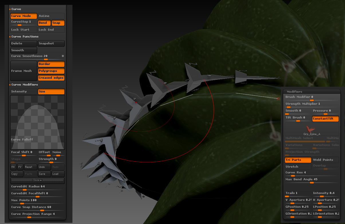
here without the Overlap setting.
here the Deph value change a lot the way your mesh is inside or outside of the Surface shape. But the random Mesh insert still didn’t work here.
So the question are there:
How to lock the proportion for the curve size mode in all the 3 axis ?
How to add more space between copy than 50 % of the mesh insert and without changing his own proportion ?
How to add a random mesh copy in this curve ? Cause i got 8 different subtool in this Multi Mesh Insert, and i want to spread them out randomly on this line.
Attachments
no answer ?
please make your own !
Hello fellow Zbrushers, while trying out the MMs the community provides, i encountered a Problem containing the Rotation i get when inserting sertain Multi meshs: Is there an Option to Change the Rotation of imms?
Hi everybody. I’m having some issues with the workflow.
EDIT: Not having any issues anymore. I finally learned by clicking in the subtool once to finalize it and the stroke disappears! 
However, can you go back and modify the mesh once it is “finalized” so to say? Go back and modify the stroke, replacing, scaling etc? or once you’ve clicked it, there’s no going back?
I assume not cause you’ve created new meshes inside the subtool itself and thereäs no history to the stroke anymore?
Is there a short and easy way to separate the newly created meshes into own subtool?
Having to duplicate and deleting is pretty annoying =/
Thanks!
Yep!
Go into the SubTool Pallet and look under Split, Use Split To Parts (this might be a bit much if you have lots and lots of “parts”). Each polygroup will be split into a separate subtool.
Each time you use a insert brush it adds a new polygroup for that stroke which you can then do all sorts of cool things with.
Thanks alot!
If your using a tri-part insert, you might not want to split that up as it has 3 polygroups, so another alternative might be to ‘Ctrl+Shift+click’ to hide the part you want to split then in ‘Tool > Subtool >Split’ click ‘Split Hidden’.
ps: Hya Mealea! 
|Sooo…
|
I have a couple of questions that are partially on topic and partly off topic but sort of related sort of…
The first part is what to do with Micromesh things, in my case I made a bit of cloth that can be used as micromesh to make some fairly good cloth, its not an insert however but its sort of the same idea, should I put it in the Insert brush repository or not? Oh, and if not where would be better? Making another thread seems a bit much but its obviously not a mesh insert (and actually screws up as one, too many poly groups I think)
The other part of the question is more complicated and sort of a request, you know how with an open ended mesh insert you can weld the open bits together? Is that possible with Micromesh and if not could it be made to be?
What I am seeing is gaps between each bit of mesh and it interrupts an otherwise potentially perfect flow.
In this example Im dealing with I made that segment of cloth but there are gaps between the segments that cause problems later like after doing BPR to Geo in the Geometry pallet.
Does this even make sense?
I can post pictures if needed.
[Aurick, if this belongs in the Troubleshooting section let me know and I will move it ok?]
Cheers!
Mealea
PS: Hya ZBER!!!
|
Hi Mealea
Something you might want to look into is ZWelder by Piggyson (Joseph Drust). I’m not a 100% sure about this, but I think he uses it in his Micromesh Hood tutorials.
OK, I just watched the tutorials again and he starts getting into using ZWelder at minute 6:55 in the Micromesh Hood Part 2 video.
|ZBer that is SO CLOSE!!!
|
I watched the whole thing, its great!
But its not quite doing it, he is using a one sided object and Im not and I think that is where I am running into problems…
Im trying to make a connecting weave that results in continuous geometry (like his does after exporting and importing) but mine has depth and the edges are not welding, also I have more than one polygroup because each thread or strand needs to be able to be edited later, what I am ending up with is each instance of the mesh I am using for the micromesh is coming out as a separate meshes (thousands of them) and that kills it.
They don’t weld, they don’t dynamesh and they don’t ZRemesh… so far.
The other thing I am wondering is whether I need total precision on the ends of the strands, this is something I have no clue how to accomplish in ZBrush, and I don’t want to make micromesh things in something else for a number of reasons, mainly I hate leaving ZBrush.
This is the file, once you see it on an object as micromesh you will see how its failing, the best way to see it is to use the smooth brush, but you can see it in other ways too such as by subdividing it.
MicroMeshCloth.zip (14.3 KB)
[ EDIT: I may be seeing some welding, but not to and from the correct points and suddenly I think I know why, that whole thing about Spin Edges, I bet that the little welding I am seeing is not happening correctly because my objects are not lined up in the same directions! If that is the case Im screwed because while in his tutorial he does this with a small grid of polygons for making an Alpha I am using full objects that have a million or so polygons. I bet that is what it happening!
Oh crap! ]|
MicroMeshCloth.zip (14.3 KB)
I confirmed that last bit about needing to use Spin Edges.
It looks like I might be screwed.
I think where you are having the problem is that you have closed geo where it should be open. If you are going to use it for ‘micromesh converted to geo’ then everything around the outside will have to be open or it might not weld properly. This is true for most 3D apps. Also, you have slightly overlapping geo and I think it is confusing ZBrush as what to weld and what not to weld.
edit: add image

This is what I get, using your ztool, when I use ‘micromesh converted to geo’ then welded using ZWelder and then subdivided twice. Is this the same as what you get?

|EDIT:
|
I tried ZWelder again and this time it worked mostly!
I think the difference was that I had not opened anything from a folder different then where ever ZWelder stores things… or something… honestly I have no clue…
I did do some welding and seems to have worked FAIRLY well, but with some exceptions where some points seem to be welded to the wrong place, this happened before but more so, I think what I need is that bloody Spin Edge thing automated somehow, I don’t quite see spinning the edges of many millions of polygons by hand… if that is even the problem!
PROGRESS!!! YAY!!!
Half of this post was deleted for no evident reason.
ZBC is a weird bit of html…
So here’s the other blasted part:
Do you mean the ends of the strands need to be open? or all of the stuff on the edges including the sides of the strands?
Your result looks great but I would love to see it after you use the smooth brush on it, using the smooth brush makes it look “threadbare” but it also shows where points weld funny…
If you have opened the sides of the strands they will merge into one wide one which is somewhat undesirable, I think that could be fixable by moving them in from the edge however. The problem there is that this is designed to be sort of dense cloth that can be thinned out later.
Hmmmmm…|
This is what I get when I smooth the hell out of it using the Smooth brush.

What I did…
-
Load your ztool.
-
Select a Plane3D and make it a PM3D.
-
Reconstruct Subdiv twice but only for demonstartion purposes to keep it light.
-
Went to ‘Tool > Geometry > Modify Topology’, clicked ‘MicroMesh’ and selected your ztool.
-
Turned on ‘Draw MicroMesh’ in ‘Render > Render Properties’.
-
Did a BPR render.
-
Clicked ‘Convert BPR To Geo’ in ‘Tool > Geometry’.
-
Used Zwelder to weld geo (no errors).
but, as you see where I used the Smoothe brush, it didn’t get welded everywhere. I don’t think that is ZWelders fault though.