ZBrushCentral

ZBrush for CNC Carving

Amost any CAD application I know of can read dxf files. Very common file format. CAM applications can then use this data to generate a tool path for machining. Seems that 3d printers almost always require stl files tho. Personally I think that the 3d printer option is best for reproducing 3d models in the real world.

regards

I think the proper tool to use for this application would be a ball nose endmill and files with a high poly count would be wasted on this application (consider the tool nose radius) . In order to get any kind of quality would require many many hours of milling making it noncost effective.

I was once a machinist and my brother owns a machine shop. I asked him how many hours it would require to machine a model of a face on one of his mills. He said about eight hours. Plus remember the quality would depend on the radius of t he endmill. The smaller the radius the higher the resolution and the greater the number of passes to accomplish the task. Very time consuming anyway. However if you had a mill tucked away in your garage it probably wouldnt matter. I have a Hardinge Horizontal mill with a Bridgeport M Head in mine but it is not cnc.

JGrimes

Hi John,

3d printing has a lot of promise. I get the impression that it’s a lot easier to produce things with a 3d printer, but they cost a lot of money compared to a milling machine. Also, the finish that they produce still does not have the smoothness that you can achieve via milling. At least for now.

You are right about the time that it takes to mill things in high detail. It takes forever! But if you have time and you only need one copy, then I think it can be cost effective. Although I imagine it would be expensive to go through a service bureau to do something like that though.

Hey guys,
Nice to see this thread still going.

Just a note about DXF: It really isn’t a viable option in todays world of CAD.
It’s only supported by most CAD vendors in an effort to help customers translate legacy data into a more state of art File type.
As I said earlier, Autodesk, the owner of the file type is neither developing it further, or providing any options for it’s use in their flagship app, Inventor, except as an export from the 2d dimentional drawing space. (Not from the model space).
I bring this to the table because this is a tiny group of folks who are trying to find a bridge between 3d CAD & 3d modelling. Finding a future for DXF is not the direction the CAD mfgrs are taking. I agree, and wouldn’t recommend spending too much effort with it.
My thoughts are to find some workflow to truely translate the Polygon data to true Surfaces. If both communities see the need and work this angle with some serious effort we’ll get there. I’m really excited to see the 3d community getting interested in and frustrated with manufacturing their models.

As to comparing CNC machining to RP, I think of the comparison as a ratio.
You have on the one hand milling; Subtractive, highest quality available, at the cost of time.
on the other RP; Additive, Quickest? Not really. Can produce a part not possible with CNC.
You need to choose your ratio in accordance with your priorities.

I just had some parts done with the SLS process, (you get a metal part). A 30 hour process! To do 1 or 25. The part was something I could NOT machine. But as a part that was suposed to look like a machined part it sucked.
The RP world makes no bones - they cannot hold tolerances that you can very well expect from a machine shop.

So I chose the 30 hour SLS process for one reason this time: I couldn’t make it another way. I’ll post some pics later.

As for the time to get near net finish, yeah man, with a mill in the garage, you can set it up and go to bed. so what’s the big deal as long as I’m not sitting out there sculpting or machining til 4:00 AM.

Hey guys,
The picture is of two parts produced with the SLS RP Process. You get a metal piece that has similar characteristics of 7075 aluminum. It’s the same file used (STL), and can be high temp silver soldered, big bonus!

DSCN0164.JPG

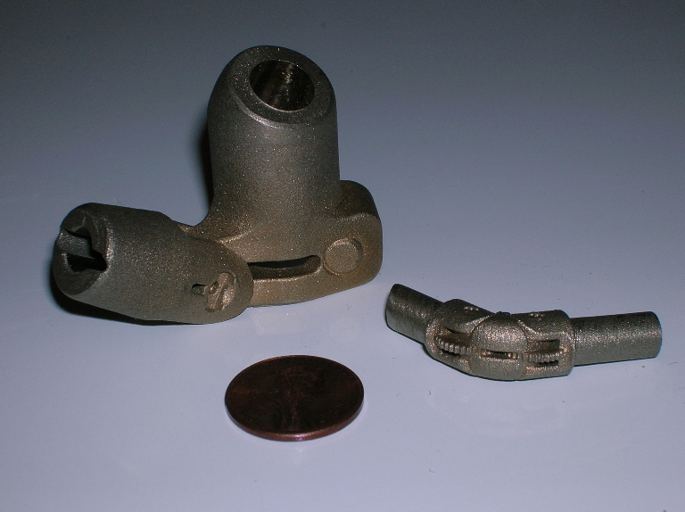
Each piece started as an assembly of individual parts in my CAD app, I had to machine these individual pieces in full scale, and create a working mechanism. The smaller of the two was 2"dia at full size.

What I did was convert the assembly into one part and scaled it down, export as STL, email off to my vendor, 30 hours later and lots of $ paid, had 36 SLS parts in hand.

Two things to look at:
For the quantity of parts it is impossibly fast compared to machining. The math comes out to 49 minutes per piece. But unfortunatly, it would be 30 hours if I ordered only one piece too. Also, I could not really get the geometry exactly like the model without some post-work.
Translation: no time to machine them.

However, The STL file was at the highest resolution. As you can see, there are lines showing the layer build-up. As I noted earlier, the parts were supposed to look like the machined (full-sized) counterpart. But given that I needed the metal part, what it looked like was more like a cast part.
From the machine this was as good as it gets.

So, hopefully this can help show how there is no one best approach. You got to try them all, then be able to decide which is best for the job at hand.

This thread rocks!
I have been a machinist/moldmaker for over 20 years and have also been involved with video games and movie making recently (last 7 years). I will be helping artist transform CG into durable objects.
I will either be using CNC mills or SLA methods depending on the size and end use of the objects.
CAD/CAM will be a combo of Solidworks/MasterCAM9.
Artist obviously from being on this board will be using Zbrush, and most likey either 3dsMax or Maya.

I’m curious on methods for texturing Real World™, as most models produced will have CG textured counterparts.

That’s part of what makes zbrush so great for this sort of application. Adding geometry based deformation is very natural with zbrush. There are lots of ways to do geometry-texturing. It mostly depends though on what you want to accomplish.

If you want to know how to do a specific thing it’s probably best to start a thread in the questions section. The practical guide is also a good place to go to get a good overview.

Wow! I thought this thread died. Since the Olympics have begun showing the spot, I guess I can show the work that used the parts shown in my last post. This model has nothing to do with Zbrush, however it does represent the topic of modeling to manufacturing.

The project took about two weeks to complete, except the first week was spent dicking around with the agency over designs. This is why we had to opt for an RP process for the parts. In the end it was all fabricated with Stainless Steel tubing and the gussets were all CNC machined by us in house. What is not shown is the entire chassis that was also made to assemble everything around. It’s inside the notebook. If there’s interest here I’ll post more shots.

ibm2.jpg

I’m glad to see this thread pick up too. So far I’m completely self taught in all of this and it’s nice to talk to some people who know what’s going on.

Hi,

having posted a question in the german zbrush forum I got the hint to look here. Wow, just what I was looking for, If you guys would live in Europe I would start a tour knocking on some doors …

I am teaching handicapped young people in arts and woodworking. clip_image001.jpg

I would like to model a chair which I did build already (see picture) in birch plywood. I have just recently started with educational versions of Solidworks and Rhino, - I can construct more simple furniture in Solidworks, but have little experience in Rhino yet. Modelling the chair in Solidworks is too hard, people told me to get Rhino for that. Others were talking about Zbrush, that’s why I did ask for help in the german Zbrush forum.

I am astonished at your knowhow, experience and skills.

What routb gets done is just what I am searching for!

I wish to design furniture prototypes in real size and material - and at the same time in Rhino (or Solidworks – and Zbrush?) – and then get it routed or milled. In case of the chair I would cut the modelled piece in Solidworks (or Rhino?) into slices which can be managed by CAM with holes provided for fitting together for being glued together. The assembly work, sanding and oiling I would like to do with my mentally and physically handicapped adolescents.

Well, I do consider to start with a third software like Zbrush for more detailed, textured surfaces (in other pieces) but I do not like to get into a fourth one like maya. I even would prefer to do without Solidworks (or Rhino?).

Hoping for advice
Best regards

Reinhold

Hi Reinhold-

Question for you: Are you planning to do the machine work yourself?
If so, the choice of modeler is only the first step.

Something that has been lost in this thread is ther difference between the homeshop user and a proffesional setup. Not that there is always a difference in quality, just that the pro setup may be more efficient, a lot faster, and able to produce larger pieces. All this for a lot more $$$.

So if you’re going to do the CNC yourself, I would suggest you look at the other end first and think about how you’re going execute the CNC. Are you going to purchase or build a machine yourself? BTW, the later is not unrealistic at all these days.

Food for thought~

Dear bpmufx,

I would like to start at the software end, i.e. the beginning. In my case I want to do the modelling (show it to my students) and then look for a manufacturer and get it milled (making an excursion and show or fotograph it for the students). Best case would be that we receive a donation to buy a little machine big enough to get a chair done.
But how would the CAM/CNC-end cause changes in the choice of modelling-software? Wouldn’t you choose the most suitable solution for your modelling task anyway? Following the thread I have learned that the data transfer seems to be the main problem: From Zbrush to Rhino for “translating” then to something else!?

Regards,
Reinhold

Hi Reinhold,

First off, your chair is beautiful! Was it carved, laminated, bent? how was it done?

I only say to consider the end application first (IF your going to do the Machine work yourself) because there are so many issues for you consider depending on your needs. And in general, the cost is much greater for CAD/CAM. Therefore if you find you’re not happy with your purchase, it will be magnified by the cost. Not only what you already paid but what you will pay for the next solution.

You’ll be fine with a modeler only, if you find a manufacturer that can work with your files. If you plan to do the machine work yourself, the need is greater for you to mate your software suite together.

For the majority of users found in this forum, the modeling is the end of the line. Also for the pro modeler found here, the file type needed to continue to bring life to a model is fairly universal with OBJ. Not so with CAD/CAM.

If your budget is tight, that will most definatly come into play at least in eliminating certain apps.

But one thing is certain, when you get to a point, you’ll see that there is no such thing as a “Silver bullet” application. I was only asking you to consider the whole “Pipeline” because in your case this does not end with a 3d modeler. And since your import export needs seem to require OBJ if you start using Zbrush, you’ll find this to be an unconventional requirement in CAD apps. RhinoCAD is a great import/export utility if you find it’s not what you want for modeling. Keep it handy. STL is an export option only but in both cases you’ll have few options to work with either file type within the CAD environment. (Read begining of this thread).

~Hope this helps

Reinhold

First of all I think you are off to great stuff!

And I think you are right, the modling software is not really connected to the router in the end.

I got involved in a little project regarding a simmilar matter and it all boils down to the fact that you cannot live without Rhino abd if you need crazy detail you can use ZBrush as an addon to RHino. Then you need a CAM to fiddle the data for the router together and that’s it. 99% of all tasks covered. So with a system around 50,000$ you are all set to produce chairs.

Honestly, I’d invest in a vaccum press and a lace ;-). The chair is done in less time and a fraction of single puzzle pieces…

Lemo

Thanks @ bpmufx: To build the chair you have to do a 1:1 design of side, front and top. Then you divide the front into vertical sections according to the thickness of your plywood board. Then sketch the pieces on the board cut them out with a jig saw, glue the pieces together (see photo) then “carve” resp. sand the shape with an angle grinder. Two hand machines - that’s it. What looks klike the grain of wood is an effect caused by the black glue of the thin layers of the birch plywood.
Detail_Plattenaufbau.gif

Thanks @ Lemo: You won’t build the chair with a “lace” (you mean lathe?) and a vacuum press :wink: - no way.
Well, I start with Rhino (the duck tutorial is done!) and when I will have the modelled chair I will find out a CAM solution - I guess.

Reinhold

If you’re interested in working with Rhino, you should look into their mated CAM package. Its made by Mecsoft. It’s real capable.

Are you hoping to continue with the 2d profiles, cutting them out with CNC? Or are you thinking of a different approach requiring 3, 4, 5 axis machining?

Hey Lemonnado, how did your knife handle work out?

Yes, lathe… sorry… I thought the chair was smooth hahaha. I’d turn the legs and then vacuum press/bend the other curved parts onto a form.

But the chair in your picture looks more like a job for my bandsaw 8-). Definitely no lathe there! haha

Lemo

PS:The knife handle was modified with Rhino. The attempt to convert the nurbs surface to polygons which could be modified nicely in ZBrush fails for various reasons. Mainly because the automated algorithms to tesselate and quadrangulate the surface do not yield meshes which can be deformed easily after the process. Using ZB to generate the entire piece would not have been that difficult. But time was of the essence. I even downloaded some nice CAM program which simulated how the ZB data would look as tool path and finished piece. Huge amount of data but looked great. I don;t know how that large amount of data would translate on the router in terms of harmonics (if at all) and other distortions but I guess the CAM should aproximate everything nicely a la ‘anti aliasing’. That’s where I have no clue how things work in real life…

Lemonnado- So I’m guessing you did not do the handle in the end? Sorry to
hear it, man, it looked cool. Just for info tho; the harmonic thing is an interesting aspect usually atributed to a stiffness factor in the machine or endmill cutter not the toolpath itself. Yeah there may be some inherant ossilation created by the toolpath, but if the machine is stiff, and the feed is appropriate, it shouldn’t translate to the part.

Something else you mentioned is worth a comment - until you’ve really checked the CAM apps graphical toolpath renderer with the resulting parts, it can be deceiving because the code used to represent the toolpath in you CAM app does not always translate the same depending on the post processor used. I can think of one example: A simple circle pocket- some controllers need two semicircles to do this. Others need only one full cirlce,
while some conversational controllers need this same circle specified as it’s own canned routine.

Hope you get another chance to work Zbrush into CNC parts. It’ll be cool to see some examples posted.

Nope, I did not make the handle. But both parties learned a lot and I am happy that I did not promise anything else than a try… Currently I am looking for a local machineshop with a router which I can abuse a bit :D. There is a modelmaker down the road. Maybe he’s set up with something I can access for ‘experiments’.
Lemo

Hey Lemo,

Check some small machine shops in your area, cause they’ll have a fourth axis
so some more trick stuff can be accomplished. The drawback may be dependent on the material you want run. Anyway there is a greater # of machine shops around than folks with routers, (at least out here in sunny CA.):cool:
Good luck