ZBrushCentral

Rendering ZBrush Displacement-Maps In External Renderers (May 9th: 2nd file added)

The concept of displacement mapping is not new, but the significant interest in it certainly is. Since the use of displacement maps is not yet a standard feature in all renderers, a certain degree of experimentation is required in order to achieve optimal results.

This thread is intended to be a ‘one-stop shop’ containing posts by ZBC members who have successfully rendered ZBrush-generated displacements maps in one (or more) external renderers.

Achieving optimal results in external renderers requires you to…

1. Generate the displacement map correctly.
2. Experiment and find the best render-settings in the external renderer.

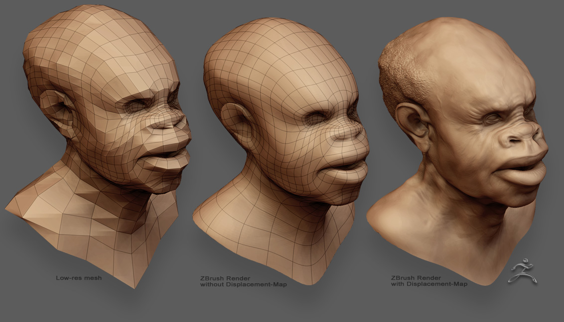
To simplify the process of finding the optimal workflow, I’m including a sample low-res head mesh with its calculated Z2 displacement map (step 1). This will allow you to concentrate your efforts on getting the best results out of the external renderer (step 2).

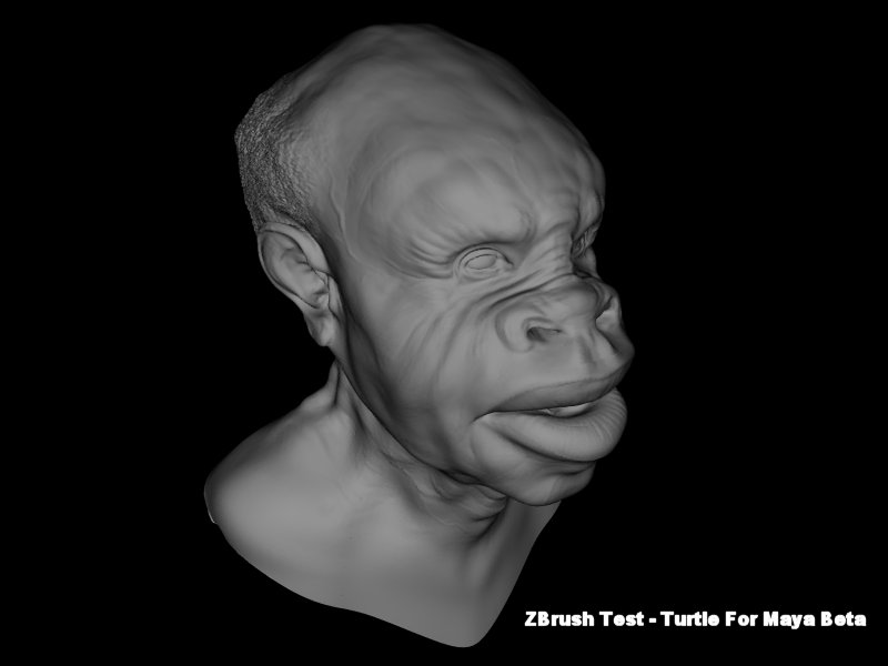
The following is the test mesh which was created, detailed and then rendered in ZBrush with, and without, the displacement-map…
user_image-1083212314xmc.jpg

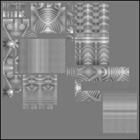
Use the link below to download a zip archive which contains 2 files: the low-resolution mesh (OBJ format) and the displacement-map (TIF format).

:small_orange_diamond::small_orange_diamond::small_orange_diamond:Click here to download the ZIP archive::small_orange_diamond::small_orange_diamond::small_orange_diamond:

Note 1: The displacement-map may need to be flipped vertically for correct UV mapping.
Note 2: The displacement-gain in ZBrush was set to 0.834; you may need to factor this value to achieve similar displacement amount in the external renderer.

Test these files in the renderer that you’re using. If you have achieved successful results (similar to the above image, in any color) you’re invited to post your findings in this thread, so others can benefit from them.

To keep this thread as informative as possible, please don’t post unsuccessful results here. If you have encountered difficulties or have questions regarding this thread, please post them in the Q&T forum.

As time progresses, the usage of displacement and normal maps will become standardized and simpler. On the ZBrush side, we will continue to enhance these features, and will continue to share information with other companies to help streamline the process of rendering ZBrush-generated displacement and normal maps in their renderers.

Thanks :slight_smile:
-Pixolator

Update May 9th 2004:

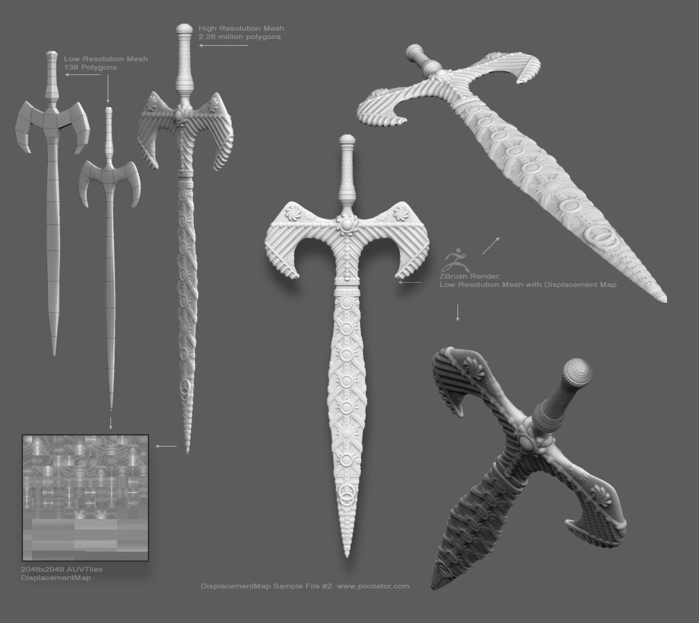
Here is one more displacement map test…
user_image-1084143678htl.jpg

This test will better enable you to evaluate the accuracy of your test-render.

This displacement test is much less forgiving than the one above due to several factors…

  1. Higher details ratio: 2.26 million polygons mapped into 138 polygons. Each low-res polygon represents 16384 high-res polygons.

  2. The displacement is composed of geometric shapes, making any mapping distortions easily detectable.

  3. The sides of the sword are perpendicular, causing abrupt changes of the normal directions within small areas.

Note 1: Since antialiasing and sampling of the displacement values are handled differently across applications, ZBrush can export the UV coordinates with or without a 0.5-pixel offset. Both files are included within the zip file. You may want to try both, to determine which one works better (i.e., is more seamless) in the external renderer.

Note 2: This test uses AUVTiles mapping. Normally, discontinuous UV mapping produces visible seam artifacts. To eliminate these artifacts, ZBrush automatically executes a smart seam-overpaint when the displacement map is generated. (The smart seam routine is optimized for AUVTiles/GUVTiles and other rectangle-based UV mapping. For other mapping methods the standard seam-overpaint is used)

Note 3: If your external renderer cannot make use of the full 16-bit resolution of the included displacement map, you may be able to improve the displacement render quality by first maximizing the grayscale contrast of the 16-bit displacement map, then reducing its depth to 8 bits.

Note 4: This test is provided because it’s a very demanding displacement map. Since it requires a more accurate rendering, some visible artifacts in your test render, especially at the sharp edges of the blade, will be acceptable. Typically, mesh/displacement map combinations are less demanding, and artifacts (if there are any) are less likely to be noticeable.

Note 5: If you need to modify the included displacement file to better fit the format expected by the external renderer (i.e., by splitting the map to positive and negative displacements, or by reducing the map depth to 8 bits), please specify these steps in your post. In the near future, I plan to write a ZBrush plugin which will enable you to specify a target application, and ZBrush will export the map(s) in a ready-to-use format.

:large_orange_diamond: :large_orange_diamond: :large_orange_diamond:Click here to download the sword test files (Alpha gain=0.286) :large_orange_diamond: :large_orange_diamond: :large_orange_diamond:

Below is an alternate (easier to render) version of the Sword file.
This file is mapped with GUVTiles mapping…

… and the displacement map generated from Subdiv level 2 (instead of 1)
which reduces the HighRes/LowRes ratio to 4096 (instead of 16384).

:small_orange_diamond::small_orange_diamond::small_orange_diamond: Click here to download the alternate sword test files (Alpha gain=0.14) :small_orange_diamond::small_orange_diamond::small_orange_diamond:

user_image-1084185891ald.jpg

user_image-1083212314xmc.jpg

This is a quick test done in Turtle For Maya.
No cool materials or lighting, just a simple lambert shaded mesh to illustrate the geometry.

Resolution 800x600, supersampled.

Rendered in 26 seconds on an AMD 2.3 GHz with 1GB RAM.

Workflow:

  1. Load the .obj file into Maya, and mark “render as subdivision surface” on the shape node of the mesh (level 3 for this test).

  2. Assign a shading group to the mesh.

  3. As displacement material for the shading group, choose “ilrDisplace”.

  4. Set displacement options to match ZBrush displacement:

  • Flip texture = yes. (ZBrush flips while exporting, compared to maya’s settings)
  • Displacement offset = 0.5 (white = positive displacement, gray zero, black negative)
  • Displacement scale. Adjust so that it matches the look you want.
  1. Render.

Easy setup and very fast!

Jacob Munkberg
Illuminate Labs
http://www.illuminatelabs.com/user_image-1083140360qvd.jpg

thanks for sharing, pixolator.
my results:
user_image-1083148066oco

Attachments

user_image-1083148066oco.jpg

Here is my test.
Rendered in Renderman.
Renders in less than 10 seconds.
No problems with banding or anything else.

Dave

![user_image-1083148026drm.jpg|650x921](upload://dHqx581wEGlbY0LTLujAV1ADAqy.jpeg)

Pixolator thank you so much for starting this thread.

Here is a test render from Maya 5 with Mental Ray

Settings:
Flip map in photoshop.
Save as a RGB Tif
Create a lambert shader with map in displacment channel.
Turn off feature displacement in attribute editor for the model.
Add Mental Ray subdivision and displacement nodes in the approximation editor

subdivision settings:
Spatial
min 4
max 9
length .100
view dependent
NOTE the min max settings here will increase render time as they are raised but they also seem to govern how much fine detail you get from the map in conjunction with the alpha gain and offset which seem to determine how much overall displacement you get in the pos and neg range.

DisplaceApprox:
Presets: FineViewHighQuality
min 0
max 7
length .250
view dependent

in the render globals set Mental ray to production quality and turn off backfaces under general settings (set to render front)

The most important setting I found was that the alpha depth is 14 and the offset -7 for this model.

Scott

hi

testing with vray

-import obj

  • apply a meshsmooth modifier to the object
  • aplly a vray displacement modifier
    set an amount of 8 and a shift of -4
    resolution to 1024
    render in 720 576 in 9 sec

ztest

Attachments

ztest.jpg

skycastle, can you please share with me the maya file you made for rendering with PRMAN? I’m trying to use a slim displacement shader and with no luck.

I assume mailing the file would be less tediuos then giving a somplete walkthru, bu if you can also guide us on the right path… :slight_smile:
thanks,

kobi

fr

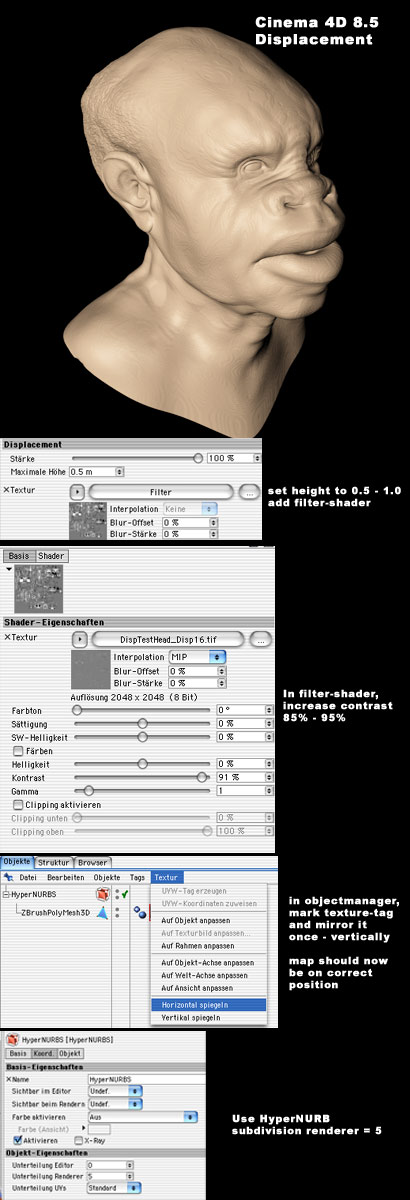
Cinema 4D 6 CE:

(Sorry, my english is poor)

I have noticed in a majority of these external render solutions, cinema, turtle, and vray, that there are subtle bloatness of features missing. I would say all of these entries so far, should be re-evaluated and updated to get a much closer match to the post that pixolator posted.

using XSI/MR here:

(hope Pixolator won’t sue me for using a transparent bg hehe)

1st…same steps as Scott used for maya MR for the format:

-Flip map vertically
-Convert to RGB (MR can’t read 16-bit greyscale TIF)

then inside XSI’s render tree,

-convert image texture output to scalar
-subtract 0,627 from that value … this seems to be necessary because “no displacement” does not seem to be 0,5 in the provided texture, but 0,627 instead
-multiply by 10 (this value must be guessed unfortunately. Continuumx— this is also why probably some of the models might look a little bloated to you)
-plug into shader’s displacement. Done


Edit:
make sure before opening the map in PS to turn OFF color management! That’s what caused the shift to 0.627 on my machine.

rray, what are your setting for displacement in xsi ? are you using fine displacement ? i have a lot of trouble getting my disp maps working in xsi :stuck_out_tongue: ( a lot of mental ray crash )

[edit] (just see that you said there are the same setting as Scott for mr under maya, guess it’s fine displacement so ^^)

okie i think i got it.
Thanks for the infor Scott.
However, I wonder how anyone would have any clue to the kind of settings that one should insert in those attritbutes …

Cinema 4D CE+. I’m so happy this works!

RRay, your settings are as close as match as I have seen. Very acceptable solution.

Fantastic render!

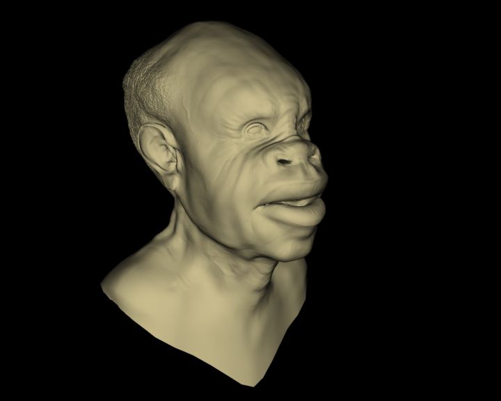
my test using the findings discovered by our ZB C4D boys. :slight_smile:

There’s some weird banding, if you look at the nose in particular.

Render times are a little high I guess because of the displacement and upped Subdivisions.

Good to see either way…looking like we can use zBrush with some creative workarounds.

Cheers!

displace

Attachments

displace.jpg

skycastle: Can you post your specs with your Prman settings?? Im doing the same tests but with uhh bad results :slight_smile: thnx in advance :slight_smile:

MAX 6.0, thats the viewport view…(and a render)
Just a meshsmooth and standard displace modifier, luminance center at 0.5 and strength=17

It just mean that if anything else fails, in MAX, you can still use max displace to get the result you want. But no micropoly displacement here…

Julien

Oh, and by the way… thanks Pixolator for the nice head model :slight_smile:

My test render using 2D mapping in Max/Vray. Look ma! No banding! Though I can now make it appear on demand, hehe. :slight_smile:

By the way Cornel, I see lots banding in your C4D displacement image. Just thought I’d quickly point it out.

Edit: Don’t know if this matters to anyone but thought I’d add it on to this post for the heck of it. Vray in 3D displacement mode looked pretty much identical to the 2D mode version. Only real difference was time. In 2D mode render time was 0 minutes 11 seconds, and in 3D mode 5 minutes 7 seconds. Quite a difference, and I was using the same fairly conservative render settings for both (very close to defaults, nothing special really).

Julien, do you happen to know if it’s possible to use maxman with max 6 and render the model as SubD?
might be nice (if I can figure out how to do it in maya :slight_smile: )