ZBrushCentral

If you want your lightwave mods to mimic closely zb models, read this.

Greetings,

After days of experimenting, I have found that Lightwave mimics zbrush models most closely only if you use the zb obj that is exported from Level 1 and NOT the morph target.

Using the morph target level object causes too many inconsistancies in the displacement, especially if you have very highly displaced polygons like spine pertrusions or horns, stuff like that.

Settings I found to produce best results:

  • Use AUV Tiles rather than GUV for the tool’s mapping. You may want to set ratio to 10 or 12 if your model from lightwave has wildly differing polygon sizes. GUV more often have overlapping uvs

  • Press check UV to see overlapping UV problems. If you even have one red polygon, it will cause rendering artifacts like sunken meshes instead of the proper raised meshes and vice versa. I started all eperiments using GUV tiles from day one. Once I traced rendering artifacts to be caused by overlapping UVs, changing to AUV tiles usually solved the overlapping UVs.

  • Export 4096 pixels displacement map FROM LEVEL 1

  • Export object again FROM LEVEL 1. DO NOT Switch morph target. (This is in direct opposition to the usual suggestion to switch morph target.).

  • Application of displacement map has been well covered by Steve Warner, so refer to his website. Only things I would add are 1) Turn off MIP mapping and 2) Pixel Blending.

  • Use the Displacement Map also on the bump channel in the shader. Here you can leave MIP and Pixel Blending on. Set the bump value to 2500% to 5000%! to see proper clarity. (May differ if your model scales are very different from mine. I used REAL WORLD scale for all my models. Meaning if the character is meant to be 6 feet tall, that will be the height of the model in Lightwave.

  • If you use the displacement map on the bump channel, you can get very good compromise with mesh render subpatch level at 7, resulting in much faster render times. Without the bump channel, you need at least 15 up to 25 for best results but loooong render times.

  • All textures are best at 4096 size.

That’s all for now. Enjoy the pure joy of seeing Lightwave models mimic its counterpart in zBrush so closely. Until Lightwave 9 that is. ONce we get true sub-pixel displacement, all these wont matter any more.:smiley:

hi

would like to thank you for posting this as I am sure it will help some folks.

also always being curious and don’t have xsi I was wondering why xsi doesn’t like the base…does it not have any kind of smoothing that can be turned on and set to a certain level so the displacements would work well or it does but it sucks? Am just trying to learn all the that might or might not become a problem for me as I tiptoe along.

Thanks so much for that, cant wait to go home and try it!

HI Aminuts,

I don’t use XSI; with Lightwave, I suspect it is because the morph target or base mesh has too far to deform when displaced. This is because modellers like me use zb to mould in stuff like spinal pertrusions, bulky bullet-proof vests, shoulder pads, etc. Yes, the model is smoothed before sending to Layout and also the shader is set to Smoothing On.

So, if you do these kind of moulded parts from the base mesh, you can see that the model even at LEVEL 1 will see quite marked topological change. If you switch morph target, you basically get back your base mesh but with the UV mapping applied. I guess using the base is asking too much of a programme like Lightwave that does not support Sup-Pixel Displacement to do such huge displacement.

That was the exact post i was looking for concidering lightwave!
Thx!
(back to studie the big oh Z)

hi Vincent,

thanks for answering my question, and sorry about the xsi…i hate it when i am thinking one thing and type another arrghhhhh. Does lightwave have any way of adjusting the render block size?

another question…would the ability to adjust the render block help or no? What I mean is I am assuming that your protrusion is exceeding one block into another when using the original base mesh and lw doesn’t adjust for these things. I am assuming I am way off here but am trying to visualize the why I guess.

LOL. Aminuts, I am a newbie! Cannot answer such technical questions. However, I am a diehard problem solver,I see a problem, I like to see it solved.

In any case, when you mention render block, you mean render block size? If yes, that won’t help as that’s a memory render issue. Here, I’m dealing with a sub-par displacement system in Lightwave. Lightwave 9 is supposed to resolve this with 32bit image capability, sub-pixel displacement and optimisation to work with zBrush displacement and normal maps.

This is the closiest I can get Lightwave to match ZB. Below is original grab from zbzb_original.jpg

Setting is Subpatch level 10 and bump map at 5000%. Render time 22seconds as opposed to using sublevel 20 with bump map. This will take about 4 minutes with not much further improvement.

Attachments

lw_22_seconds_bump.jpg

Thanks for the info, Vince! Your’e a lifesaver…a cherry one…The best…:lol:

Dickie

Turning off MIP for the BUMP channel and setting subpatch to 15 and above will give slightly more definition. Since I’m trying to key down my workflow for LW-ZB, I cannot waste time waiting for things to render.:slight_smile:

try to add some contrast to the displacement map (in LW image editor or PSP)

Great post Vincent1. All tips about the pipeline between these programs are more then welcom. :+1: 
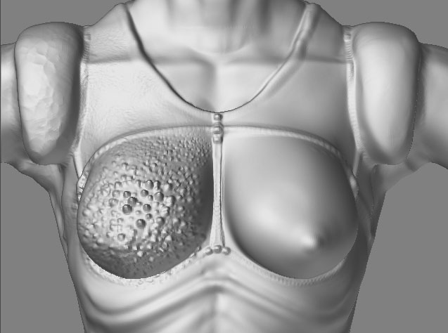
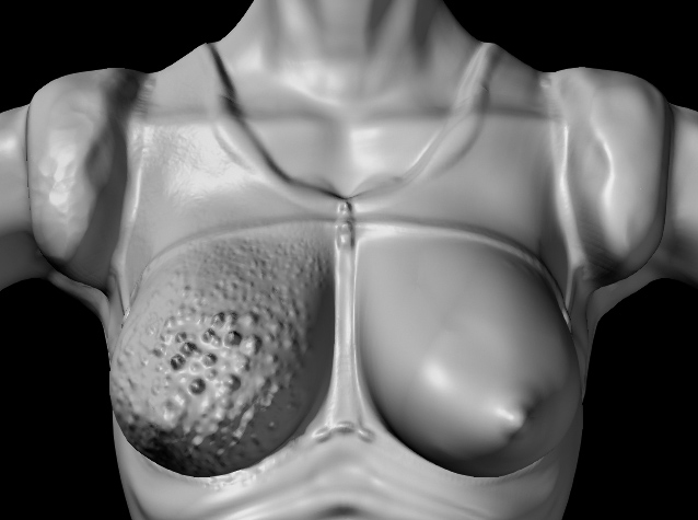
Naturally, when I bought Zbrush a few weeks ago, I started importing and exporting like hell between LW & Zbrush. After a while (and with the help of Warner’s advice) I got good results. I kept one problem thought; with models made in LW, exported to Zbrush, and finally exported back to LW, I tend to get weird results at the edges of my object, like so:

bodytrouble.jpg

Have any of you come across this problem? When I have time I will try you’re tips, and see if they help.
I don’t quite understand why you should use such high subpatch-levels without bumpmaps. I generally find my displacements working fine at level 6/7 without a bump map (above images excluded :wink: ), and personally I prefer normalmaps over bumpmaps for getting nice detail. From what I’ve heard LW 9 is going to incorporate real Normalmaps, and with the subpixel displacement and all I predict countless hours lost with blissfull importing and exporting once LW9 is out… beware! :smiley:

Attachments

shoetrouble.jpg

Could be a number of things:

Check for 2 point polygons, they are created when you weld vertices together. They look like straight lines. Check your info window (press “w”) in lightwave.

Check for coincident points, i.e. points that lie on top of each other but are not welded. Try a merge.

May be caused by three point polys.

I had to redo models to ensure they were all quads, good discipline to maintain all models as quads.

Edit: Did you check your uv for red polys in zbrush?

Alas, those shoes are made of quads, and there were no double points, I did the UV check and not a single red polygon appeared. When I check the POINT statistics in LW, I have a few 2-point groups in the problem-area’s, but is that is not the same as having 2-point polygons in your POLYGON statistic window, isn’t it?
Here is how the model looks in LW:

LW-shoes.jpg

Due to some reason I worked on a very small scale with this model: the whole figure is not more than 10 mm long. I usually don’t bother with it, because for the LW camera, size doesn’t really matter. But perhaps this small scale is causing the trouble, though I don’t see an good explanation for that…

That could be it, as displacement happens on xyz space. You could scale up the model and see if it helps.
Or since it is a simple mesh, perhaps fold out the edge and see if it distorts. Sometimes I have encontered polys that for no apparent reason refuses to shade and render properly; the only fix was to delete those and surrounding polygons and rebuild.:cry:

Why does the polygon flow look so odd and the mesh so straight at the back? I think the “Y” branching is redundant. Spinquad and merge polygons should resolve that area.

It is a good idea to alway model in real scale because once you move into GI and Radiosity renders, scale will effect your light renders.

Well, those shoes were the result of a “IGOTZBRUSHNOWLETSSEEHOWFASTICANBUILDAHUMANCHARACTER”-frenzy, hence the insane small scale and poor polyflow. Good polyflow is still something I must teach myself to focus on. Kind of the holy grail in modelling eh? I scaled up the shoes, but the problem stays. It looks like the displacement is causing the inside edges of the shoes to curl through the backside, though they don’t do that in Zbrush. As you can see on the earlier pictures, same happens at the end of the sleeves (don’t recall the English word :o ) and at the ‘end’ of the trousers. I would like to know a way around this problem… But perhaps these are just the stubbourn poly’s you mentioned. We must teach those bastards a lesson; “Bad poly’s!!” :mad:

Hey vincent1,

I’ve also found that using morph targets in Lightwave for facial animation or muscle flexing causes some weird stripping effects when animated. Have you encountered this?

HI Jay,

I have done simple morph target for eye blinks, eyebrows and body shape shift; no problems so far. These are of course very basic movements so may not be representative.

My Walk cycle shows no apparent problems yet.

thaaaanks vincent for beginning this convo about refining the pipeline started by Warner.

he did lay the grounds for it, but there are still many issues and artifacts we’d all like to avoid.

lets keep this up… i will contribute anything i can via testing… and yes… cant wait for LW9

question… when you say you use the OBJ that was directly epxported out of zbrush… do you mean always using that OBJ from that point on? … nevewr bringing it into modeler and saving it again as an lwo?

this of course omits any use of zWave hmm?

also… i have a real bad artifacting problem that I haven’t seemed to find a solution for… it happened months ago while working on a project, and now is appearing again in my renders.

here is a link to a thread where i posted pictures of it
http://www.zbrushcentral.com/zbc/showpost.php?p=224985&postcount=23

vincent… have you come across any issues like this?
your results are incredible… i have never had such fine detail in my zbrushed LW models before… do you think it has anything to do with too LOW a poly cound in my base meshes? … meaning that the fine areas of my meshes get very fineley subD’d but my areas where there are large poly’s… do not… and therefor suffer from lack of geometry to deform?

i am in texturing phase of my charcter and am trying to get all the kinks worked out for it. i have been dealing with all the ZBrush-LW discrepancies for about a YEAR now… and have yet to produce an eye popping animation in LW using a very detailed zbrushed character.

im also not comfortable with the way the nurbs work on my OBJ file when compared to my origonal LWO file. …tkae for instance the antelers on this dragon i am making now… the OBJ versions’ are about 25% thinner than the ones in the LWO file… the cuves created by my subD’s seem alot tighter than i origonaly modeled them to be. this causes for some differences in the model that i dont want.

Hi,

You still have to save the LEVEL 1 obj to a lightwave obj before you can send it to Lightwave Layout.

From what I can see, your model has not been subpatched before sending to Modeler. If you are working for game engines, then displacement maps wont help, you need to do normal mapping.

If not for games, my steps are these:

  1. With your model down to LEVEL 1, select texture under Tool menu and click once on AUV tiles.
  2. Export your obj from ZB at LEVEL 1. Do NOT switch Morph target.
  3. Export your Displacement Map also from LEVEL 1. Use 4096 map size. Once calculations are done, select Alpha, click the displacement map and click “Flip V”. Export as tif file.
  4. In Lightwave modeler, import the ZB LEVEL 1 obj model.
  5. Press “tab” to apply subpatch to the model.
  6. Press F5 to bring up surface window and click Smoothing to Selected.
  7. Save as a Lightwave Obj.
  8. Send to Lightwave Layout.
  9. In layout with your model selected, Press “p” to bring out your Properties window. Set your Display Subpatch level to 5, Render Subpatch Level to 15 and above, depending how much time you have, higher the better up to 25…
  10. Click Deform Tab and add your Normal Displacement plugin. I use the one from Steve Warner’s site. Double click plugin to bring up window. Set displacment to 120mm this 120mm value will also differ depending on model, Cahe Gemetry selected, Evaluate world Coords, Use displaced Mesh Selected, LUMINANCE CENTER to 50%. THIS IS VERY IMPORTANT, ANY LESS OR MORE AND IT WONT WORK PROPERLY.
  11. Click the Texture button, Projection is UV, UVMap is OBJ_UVTextureMap, Image is the displacement map you exported from ZB, Width tile and Height Tile is Reset, Pixel Blending is OFF, MIPMap Quality is OFF.
  12. Press F5 to bring up Surface Editor. Press “T” on the Bump channel and set the parameters as for the Displacement above in Step 11. Back to Bump channel and set your Bump value to 5,000% to 8,000%. This is not a typo error.
  13. Press F9 and voila! Enjoy.

Further notes:

a) Bump values will differ depending on the scale of your model. All these values work for my REAL WORLD Scale models.

a part 2) For further enhancement, you may or may not like it; click your bump texture in Surface Editor, click “Edit Image”, click “Editing Tab” in the window that pops up and set the “Contrast Slider” to 0.18 to 0.35. Enhances the detail further. Tip courtesy of ZB Forum friend.

b) Each time you do extreme displacement deformation in ZB, you will have to repeat Step 1 to 7. This because I think the new deformations messes the AUV tile structure and if you don’t repeat Steps 1 to 7, you get brush strokes out of place, weird gouges in the surface, etc. But if you do repeat Steps 1 to 7, the model and render works out fine 100% of the time.

c) FINALISE YOUR MODEL AS MUCH AS POSSIBLE IN LIGHTWAVE. Have to shout, this is really important and a good discipline to stick to. This is because adding horns in ZB when your model has no horns in Lightwave is a BIG NO NO. The render wil be flawed as the polygon structure will show no matter what subpatch level you set to. I think this is your problem. When I mean horns, it are the ram type of horns you try to brush out of the hornless head of the model from Lightwave. If you add horns usingmulti marker, that’s different as then you will add new geometry in ZB and this added geometry will be reflected in the model at LEVEL 1. This is one good advantage of using LEVEL 1 instead of Switch Morph target.

d) I had the same problem with Zi (My Ninji Cop model). The model has no high heels but is modelled as if wearing high heels, i.e. standing tip-toed. I said to myself, “I’ll deform different heels for her in ZB”. Good idea in theory, bad in practice. The heels don’t deform nicely in ZB and looks worse in Lightwave. This is because my model is single mesh and I have not enough memory to set Subpatch Level in ZB high enough to give me enough polygons to extract the high heels. It is bad practice anyway. Surface details like raised seams, gloves, reasonble spine deformations, muscle and vein strctures are not an issue though as there are enough polygons on the surface. Just don’t expect even ZB to extract a tree out of one polygon.

So my work flow now is:

  1. Finalise model in Lightwave.

  2. Add all detailing like costume, armour, muscle enhancement, boots, gloves, etc in ZB.

  3. Paint and texture in ZB. I just love the projection painting in ZB.

3a) THEN only apply weight maps, etc. This is because each time you export to ZB or ZB exports an Obj, the weight maps are lost. Zwave allows zb UV to LW but not the other way around, which is what we want. Maybe it there in zwave, I have not looked deep enough yet.

  1. Render and/or Animate in Lightwave.

  2. Smile and go to sleep.

  3. Repeat step one. :slight_smile:

Edit: Note on the 120mm level for displacement, this will vary depending on deformations you are asking zb and lightwave to do, Example, my Zi model without the heels looks fine at 50mm displacement, but with the high heels version, it needed 120 mm before the heels extruded to the right level. Looks ugly anyway, like the tris on your model.

You need to know, because too far a value in Lightwave will cause slightly odd looking deformations like a puffy look, etc. Perhaps like the too tight curving you mentioned?