Much appreciated Wyatt. Thanks.
Awesome, can’t wait. And again, nice sculpts and cool renders!
Attachments

Attachments

Attachments
Attachments
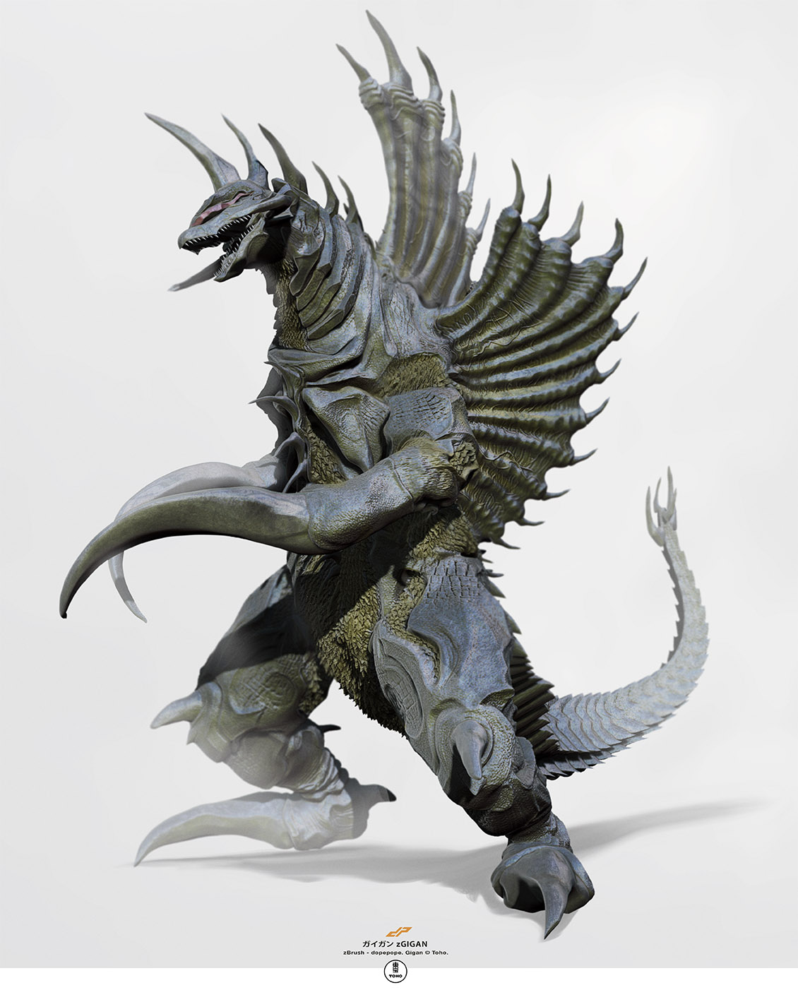
Gigan! One of my favorites.
Everybody loves GIGAN!

Attachments
Attachments


I need to create a figure for print that fits into the size illustrated here. 2.5 inches tall, 2.25 inches wide, and 3 inches long. How can I begin this project so I know my sculpture won’t exceed the measurements, or be too distorted within? Forgive me if this is basic knowledge, but I can’t seem to figure it out.

Attachments
sorry but inside zbrush is that not possible so far i know.
you must create it with 3dsmax or something like that, than import it in zbrush. but dont forget to give the right size in 3d printexporter
@ dopepope
I do this kind of sizing work every day so its doable. there’s a few ways you can work.
if you have a size you want to work with initially and you want to establish that without using another program you’ll need to create a cube. make poly mesh 3d then go into
Geometry - size and punch in the relative size there. so X 2.25 Y 2.5 Z 3. then go to 3d print exporter and set up the size in there correctly
(update size ratio and adjust the values if needed). then export as .OBJ. go to a new poly tool ( i normally use the star) and import the cube.
This establishes the size inside of zbrush so if you use the transpose tool to measure something say a thickness it will be the correct size within zbrush.
you can even if needed go to preferences > transpose > set units so it will actually display the length.
IMPORTANT NOTE. if your using inches it decimalizes it so save your self a headache and work in MM.
now if you sculpt your piece within that cube you’ll know it will fit. though to be honest if you just make sure when you export using 3d print exporter and all the values
are on or below your max size it will fit. z brush doesn’t distort the sculpt when sizing in 3d exporter.
also if you use display properties> and flip. you can flip the normals so you can see what fits and what doesn’t within the cube.
hope this helps
Well you can make that cube what ever size you want. The just make sure your sculpt fits in the bounds of that cube.
Then when you are ready to print for export, hide all of your models (subtools) but the cube and go to the ZPlugin area. (Dock it off to the side.)
Now open the 3D Print Exporter and use the “Update Size Ratios” button. If you are working in inches change the newly created values for XY and Z to what you need. (in your case just change the largest dimension you see to 3, for three inches and the other lengths should auto update for you.)
Now once you have the size of your cube established, all the other subtools will be “scaled” accordingly at export time. So I have been using the “selected” button for export. You can use “All or Visible” if you wish, but I wanted to print all parts as separate objects. So I use Selected and OBJ as my export type. Then I import that into PreForm (FormLabs 1 3D print software.) and everything is sized correctly for me.
Hope this helps! 
Oh great! Thank you all so much for responding. I think this is exactly what I needed to know. I’ll report back when I know for sure if it worked. Thanks again! ZBC is the best !
… I think it’s neat how Zbrush has a “More Than One Way to Skin a Cat” openness to it. c4th and NickZ both have solutions to the issue, so I’ll also post my procedure just to add to the options available:
-
Choose the Polymesh3D tool in the default list. It looks like a star. Draw it onto the canvas (hold shift to align it to 45 degree angles) then hit ‘T’ to Edit the mesh. It might be a good idea to turn on the floor grid, so you have a point of reference. Since it’s already a Polymesh, you can skip the ‘Make Polymesh3D’ step.
-
Under the Initialize options in the Tool Menu, set it to QCube (resolution doesn’t matter, but setting it to 1 makes things easier).
-
Activate a Transpose tool (Move will work fine) and draw a Transpose line along one edge. The start and end points should snap to the corner vertices.
-
From the Preferences Menu, find Transpose Units. Press the ‘Set Units’ and type in “Inches”. You can leave the Set Minor Ticks alone, or type 4 to set the Transpose Line to show a minor tick every quarter-inch. Set the ‘Calibration Distance’ to 1, and you’ll see in the upper left corner that the Transpose data is showing the line is now 1 Inch long.
-
Adjust the size from the Deformation options in the Tool Menu. Click each axis so you’re only working in one at a time, then type in numbers until your cube is the size of your bounding box. (In your case, I found you need to type the following values to get your cube:
Size X: 100 [enter], 12.5 [enter]. This gets you 2.25 Inches in the X-axis
Size Y: 100 [enter], 25 [enter]. The Y-axis size is now 2.5 Inches
Size Z: 100 [enter], 50 [enter]. And that will make your box 3 Inches along the Z-axis.
- Under Display Properties in the Tool Menu, press the ‘Flip’ button to flip normals so you can see the inside of your box to determine whether your models fit the bounds.
Now your bounding box is all set, follow the previous posts’ instructions when exporting for final print.
Note that this procedure fits models for Y-axis Up printing. Some printers and print service bureaus use Z-axis Up, so you’ll need to rotate the box and/or make other adjustments depending on your circumstances.
Excellent! Thanks for that in-depth guide.