This is a phenomenon I’ve actually been experiencing for several years with the 3.x topology tools, but I happen to be working in 3.5 now for the purposes of this issue, and have finally gotten a good illustration of the problem. I welcome comments from anyone pointing out that this is actually just me being stupid somehow
Drawing topology and applying a thickness to it in the Topology palette is a very powerful modeling method in Zbrush, especially for creating the sort of hard edged, mechanically precise sorts of shapes with clean, manageable geometry you would usually look to a traditional modeler for. However, the "thickness" function continues to be hindered by some reliability issues. I believe it frequently somehow corrupts isolated normals or tangents, but not in a way that is always immediately apparent.
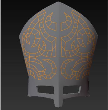
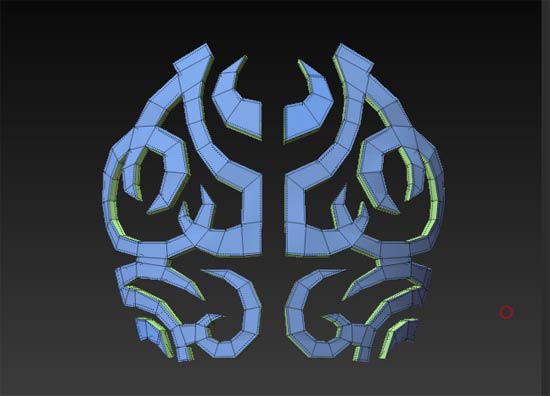
Here is a clearcut example. I am drawing some topo out on a reference shape. So far so good. (see first out of 4 images).
[attach=162371]ME1.jpg[/attach]
Max Strip length set to 4, Adapative skin subdivision set to lowest so there is no extra geometry to confuse the modeling and I can easily spot any missed targets and it looks good, all one logical polygroup.
[attach=162372]ME2.jpg[/attach]
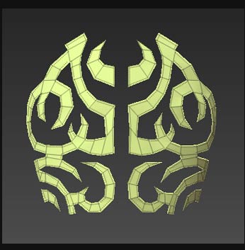
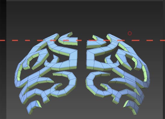
When I add some Thickness though, two of the poly clusters on either side get inverted. No Adaptive skinning controls, or switching to classic skinning make any difference.
[attach=162373]ME3.jpg[/attach]
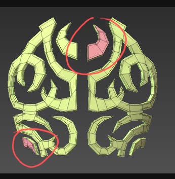
In *this* case,the problem is apparent, and it is a reasonably simple matter to fix it , either before or after mesh generation, by masking out the "good" portions on either side at the same time, and hitting "smart resym".
The problem is, I believe the same thing happens frequently when using thickness, and the issue *isn't* immediately apparent, until after you generate the skin, and it is afflicted by "random weirdness". The shape may be much more conventional, without the discontinuous poly "islands" I have here, and the polygroups seem consistent according to color coding, but I still think a few polys here and there get "twisted up" somehow, and it makes for odd issues.
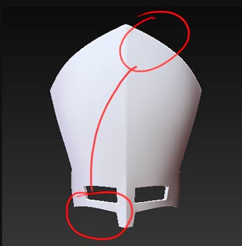
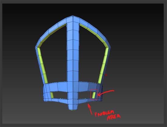
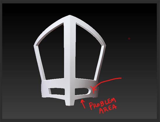
For instance, the reference mesh object I created via the same method, gave me a lot of problems when trying to get the edges creased. I would hide all but one double sided polygon on one side of the mesh, making sure nothing else was visible, apply a crease, and something else would become creased on the other side of the model , while my intended polygon was not creased.
Coincidentally, perhaps, the two "problem areas" on that mesh were in the same rough geographic location as the issues in the first example:
[attach=162374]ME4.jpg[/attach]
But I have had these odd sort of issues with many objects over the last couple years, generated in this manner. Problems range from polygroups that don't hide in the manner they are supposed to, or actually behave as if they're grouped with another polygroup, despite the color coding... as well as the same sort of creasing issues where I crease one thing, only to have it mysteriously appear somewhere else, and then the reverse happens when I try to fix that area....or polygons that won't crease no matter what I do, and I have to crease them indirectly, by creasing the edge of the surrounding polygons instead. When I encounter these kinds of quirks, I always scan the mesh for flipped normals with double sided polygons off, and even test flip them, but I can never discover any outward indication of any inverted geometry anywhere.
Anyway, it is something that has bothered me for a while now , as it tends to make the already somewhat fidgety creasing method in Zbrush a little more frustrating at times. I'm sure it's not the kind of thing that every or even most Zbrush users would encounter, depending on how they are modeling their meshes.
I just believe that the topology tools are where the real potential for Zbrush as a modeler comes into play, more so than Zspheres, and would appreciate it if this behavior could be looked into for some subsequent update.
Thanks for listening!
Alright, just to drive home my point that it is not always apparent, and I may have gotten lucky to see that flipped poly grouping…after doing a little further tweaking to the topo, now it is previewing correctly in terms of polygroup color coding…
[attach=162383]ME6.jpg[/attach]
..and it would be easy to miss, but if you tilt the tool ever so much, you can still see the mesh in the problem areas is extruding in the wrong direction:
[attach=162384]ME5.jpg[/attach]
The generated mesh previews with no flipped normal abnormalities when checked for with Double-sided off, and flipped back and forth, yet clearly there is an issue, and I probably wouldn't have noticed it otherwise, especially if the mesh were more conventional and continuous. and looked consistent to all outward appearances, yet something had still become flipped or twisted in some manner.
Attached is the slightly updated tool that exhibits the new behavior, if anyone at all cares ;)
Alright, I’m pretty sure I’m talking to myself at this point, but just to further illustrate these sort of issues that result, I need look no further than the very next mesh I generated in this manner.
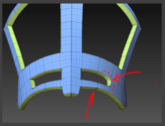
Here is another mesh generated by drawing topology and adding thickness. I have managed to isolate the two “problem areas” (there are usually two linked areas that give trouble).
[attach=162539]ME7.jpg[/attach]
Ive managed to get everything creased except for my offenders here…that lone polygon on the right side of the “eyeslot” on the right, and the area underneath it. If you divide it now, it all looks good except for that right side of the eyesocket that needs creased yet.
[attach=162541]ME8.jpg[/attach]
So I isolate that lone polygon and apply the crease function to it.
[attach=162543]ME9.jpg[/attach]
The result is, not only does the crease on that polygon not “take” (it remains uncreased), but that seemingly random area underneath it develops an undesired crease.
[attach=162545]ME10.jpg[/attach]
Now, I’ve become adept at working through these issues, and will probably be able to experiment and find some combination of alternate edges to get the necessary creases, or at worst, get one side right and mirror the creased effect at high subD level. But it further complicates a process in the program, that frankly, doesn’t need to be any more complicated.
Attached is the Problem tool in question at the stage as depicted in the first image, that I’m confident the issue can be reproduced with (Ive done so several times).
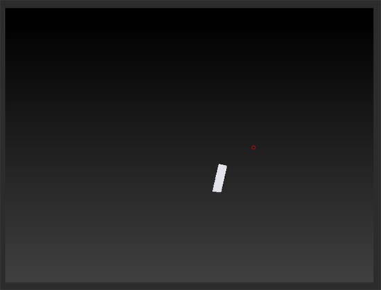
Hi Bingo, ran across your thread while researching the same inverting thickness problem myself. After experimenting a bit I seem to of found a workround. When you start to retopologise a shape e.g you’ve clicked rigging - select mesh then clicked edit topology.
Z sphere a simple shape. E.g. a long rectangle (pick a thickness, preview it (dont know if this step is necessary but if it aint broke). Now delete the shape. Now start to retpologise what you want and it seems the thickness will preview in the same direction.
It seems the first shape you create will always thicken in the opposite direction to any others so just delete that first shape. Hope that helps.