ZBrushCentral

Topology Overlapping with Dynamic Thickness

Is there a technique or setting to avoid overlapping topology when using Geometry >> Dynamic Subd >> Thickness where sharp angles are involved?

Here is an example of a lip line with thickness added (negative -100 offset),

I suspect that leaving these internal bits will cause problems in printing or elsewhere.
Dynameshing eliminates the problem but prefer to avoid that if possible.

Thank you!

Screen Shot 2020-12-29 at 7.51.02 AM

PS This is a great feature

Hello @artmaker

This is inevitable with the angle of the geometry being extruded. At some point it will converge and overlap unless you intervene.

First you have to decide how much you want to care about it. If you are going to remesh your tool or this particular subtool at any point–and there are plenty of reasons why you might–the remeshing process will probably remove that overlapping geometry since it is in the interior of the volume. A Dynamesh, Live Boolean, or Gizmo “Remesh by Union” operation would all remove geometry of this nature. This is definitely the way to go if you’re planning on decimating your model, as export topology quality is less of a concern in Decimation scenarios. If you weren’t planning on Decimating, you would probably want to retopologize your mesh after for better quality topology with ZRemesher or otherwise.


If you can’t live with it, here are some options off the top of my head.

  1. Extrude your geometry in the other direction (a positive value), if that is possible. The geo will not converge going the other way.

  2. Set your Dynamic Subdivision thickness value to a smaller amount that stops just short of the point of convergence. Apply the Dynamic Subdivision to convert it to live geometry. Mask the polygroup of the converging geometry–the purple-ish polygroup in your image–then Ctrl-click on empty canvas to invert the mask so that every other polygroup except the target polygroup is masked. Then use the Edge> Slide > Edge Loop Complete or Edge Loop Partial (it should make no difference in this scenario) to slide the edges near the corner further away from each other so they won’t converge. You can then use Polygon> QMesh> Polygroup Island while holding down Shift after starting the operation to extrude that polygroup the rest of the way along its normals. If you hold down shift, it will only move the group, and not extrude new geo.

  3. Convert to live Geometry as above, and delete the offending polygons until you have two edges that are almost connected, and use the Tool> Geometry> Modify Topology >Weld Points function to weld the two edges together. You may have to increase the tolerance until you find the minimum value that results in a weld.

Good luck! :slightly_smiling_face:

@Spyndel – Thank you!

The Gizmo “Remesh by Union” (which I had never used before) worked just fine and was easy.

Thank you for that tip and all the other ideas on fixing those issues.

Cheers!

I know this is an old post now, so I’m wondering if there’s a better resolve for this kind of issue that arises when adding thickness? I find this happens often, but is resolvable using workarounds like suggested here.

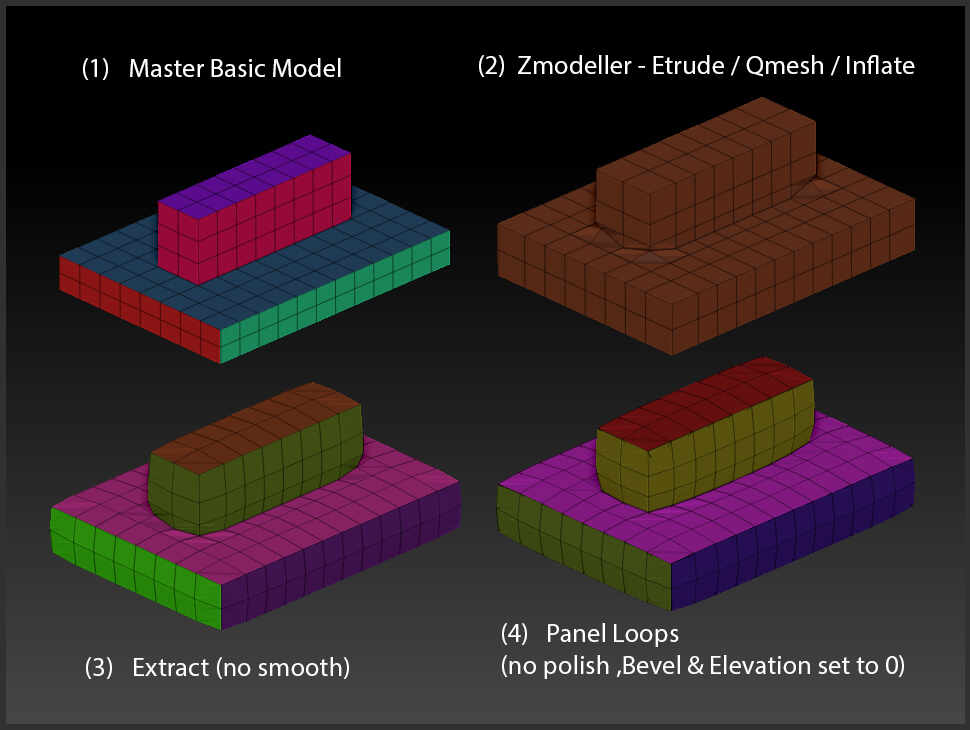
However I find wherever there’s a tight 90 degree corner, the model collapses and crumples up on itself even on thin sections. Please see this image I put together to show issues (and methods) I’m currently trying to resolve whilst adding thickness to a model.

based on model ‘1’ the results all crumple up in the 90 degree tight corners. Any ideas without Dynameshing to keep this model as a Polygroup? (remeshing is optional)

Any advice would be much appreciated.

KEY EXTRUDE 2