ZBrushCentral

Strange Zbrush Normal Map Artifacts?!

Hello,
I’m currently bringing a head created in Zbrush into Maya. I created a displacement and normal map for the head. Hooked it all up in Maya and did a test render.

This is what I got:
R_Bump.jpg

I haven’t got a clue why Zbrush has done that! Does anyone else have an idea?

The head was originally Zspheres, exported for low level modelling and then brought back to Zbrush for mid and high level sculpting. UV mapping was done with Zbrush’s AUVTiles. Normal and Displacement maps were created at 2048x2048 with ‘Adaptive’ activated.

Any help would be appreciated.

'regards
SJ64

Attachments

Z_Plain.jpg

Z_Normal.jpg

Am learning myself, so no solutions but a question…

can we see your zb generated normal map by itself and not on an object? I am curious myself why this would happen so would like to see original…as I am trying to absorb all I can to avoid future pitfalls.

Thanks in advance!!

Sure.
But with AUV tiling, I don’t know if you’ll be able to make much sense of it though?

ZBrush_Normal.jpg

SJ64

ok, some other questions…i hope that my inquiries also help to narrow down suspects so please bear with me.

“The head was originally Zspheres, exported for low level modelling and then brought back to Zbrush for mid and high level sculpting. UV mapping was done with Zbrush’s AUVTiles. Normal and Displacement maps were created at 2048x2048 with ‘Adaptive’ activated.”

I assume you exported/imported to maya for the low level modelling?

Can i ask what it was you did for the low-level modelling in maya? Steps if ya remember or something close if ya don’t.

ummm shoot I had more but ya got lucky…i am supposed to be sleeping now so brain is not working anymore hahaha.

oh…also…

what size texture did you use to create the auvtile uv’s at? I ask cuz I am not sure for one what you created em at, two am not sure off the top of my memory if you have control over the size of the created normal map as ya do with the displacement map…so would ask if it’s possible you created the normal at a higher level than the original uv map? ummmm shooot i had another…oh well I have annoyed you enuf for now.

Hi,
Thanks Aminuts for your prompt help. Sorry I took so long to get back to this (stupid work getting in the way of personal projects).

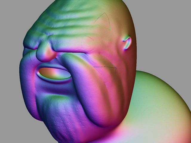
I tried a whole lot of different things. I reimported my original OBJ into Zbrush, did some random sculpting, calculated some new normal maps - Problem was still there.

Redid the uvtexturing with various ratios of AUV texturing. Interestingly this changed the artifacts, but didn’t totally remove them.

Knowing there was now a link between the UVtextering and the the artifacts, I did some reading around on these forums and it occured to me to try a larger map size. I’d been using 2048x2048, I tried 4096x4096 and it worked like a charm.

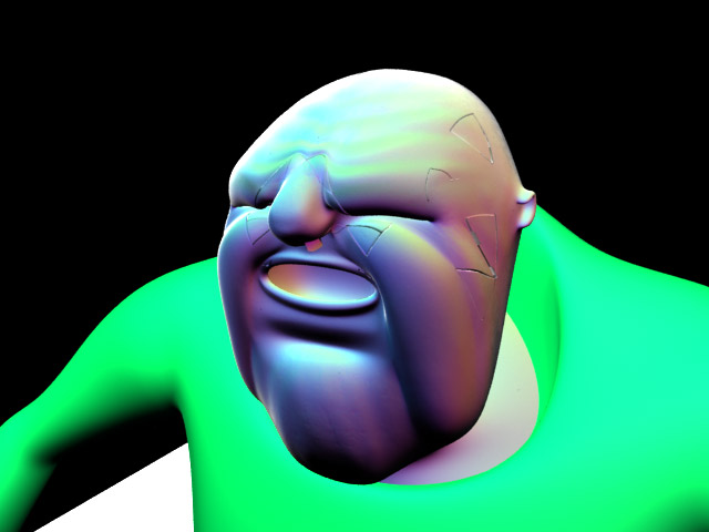
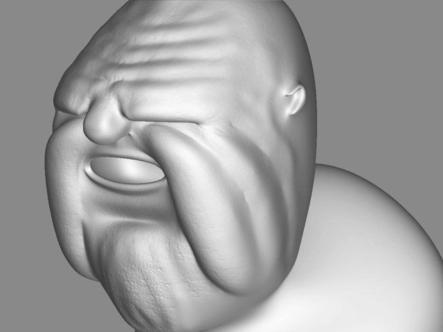
The results of my experiments can be seen in the thread:
Rendering Displacement with Renderman
http://www.zbrushcentral.com/zbc/showthread.php?t=25550

This however has raised another query for me. I had assumed that the AUV ratio simply controls how large a single uv tile can be in relation to another. I.e A ratio of 10 means that the largest tile is no larger than 10 times the smallest tile. -And that when I look at the uv map, I can see tiles that are at most 10 times larger than other tiles.
However what I’ve now read (It was a posting by Aurick) is that with an AUV ratio of 10, a single uv tile can encompass up to 10 times more surface area of a mesh than another uv tile. -AND that when I look at the uv map the two tiles occupy the same amount of area on the map.

The description in Zbrush for AUV Tiling says that larger polygons are mapped with larger portions of the texture. Hence I thought I was getting a much more uniform uv mapping - but apparently this isn’t so.

Auricks quote that’s making me confused is:
“First, what UV mapping did you use? Bump maps are a bit more susceptible to seams than texture – especially if the adjacent sides of the seam are different scale. For example, AUVTiles with a ratio other than the default of 1 can result in one side of a seam being one scale and the other side of the seam being up to 30 times larger. This then results in a visible seam when the bump map is rendered. So if you’re using AUVTiles for a model that is going to be bump mapped, it is a good idea to not use a ratio other than 1.”
In the thread: ‘seams on uv borders’ by Diamant.

Could someone explain this to me?

'regards
SJ64

Your original understanding of the ratio was correct – a higher ratio means that larger polygons appear larger than smaller ones on the texture map. However, this can also result in two polygons that are side by side being at different size ratios. For example, polygon A may be at the factor of 1 while polygon B right next to it might be at a factor of 5. This means that the details on the first polygon will be at a different scale from those next to it by a factor of 5. This in turn will tend to accent the seams when applied as a bump map.