ZBrushCentral

Rendering Displacement with Renderman

Hi,
I’ve found little information for displacement/normal rendering that is specific to Mtor Renderman. So I’ve struggled through and here is a technique that works well for me.

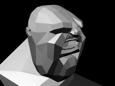
First off, my head model was created with Zsphere’s, moved to Maya for low-level modelling and then brought back to Zbrush - subdivided several times (up to 7) and then sculpted. I used ZBrushes AUV uvmapping process.

Once I was finally happy with my model within in Zbrush. I then created a Displacement and Normal map.

(I could have just created a Displacement map. However creating a single Displacement map with the amount of detail that I had took far longer than what it did to render the two maps. Also if I want to sculpt wrinkles within Zbrush to say… accompany a ‘frown’ blendshape for Maya, then I all I have to do is create a new Normal map and leave the Displacement as it is.)

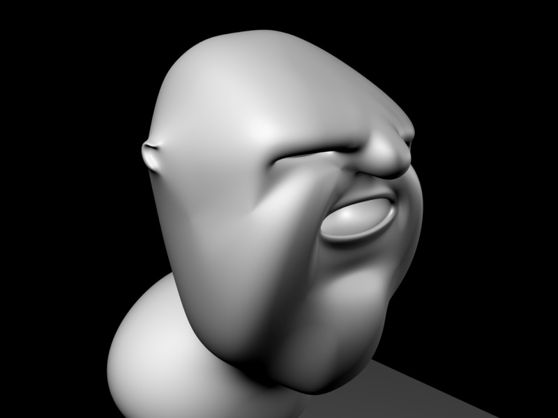
All up I went to seven levels of subdivision on my head mesh. (SubD_1: 460polys SubD_7: 1.8Mpolys) I picked SubD level five as my split point for my two maps. (As I start to animate in Maya, I may find that a different level will be better.) So for the Displacement map, I took my mesh to SubD5 and deleted the higher subDs. My settings were 'Adaptive, 4096, Intensity:0, Mid-value:0. (On another mesh of mine, a 2048 resolution yielded good results, however I had to use 4096 on this mesh because for some strange reason I was getting artifacts on my map at 2048 resolution)

This map goes to the Alpha and from there I have to flip it vertically and more importantly I have to adjust the curve for the Alpha.
I couldn’t workout how to setup a midpoint for a displacement map in Mtor, such that values under a certain grey point would be negative displacement and the others positive displacement. Instead in Zbrush I open up the Alpha curve adjustment and load a curve for it: NegativeDisplacement.ZCV. (You can find this in ZCURVES inside the ZBrush program folder) This creates a map where black is the zero value and all the greys are the negative values. Export this processed alpha as a tiff, don’t forget to press the little ‘Ep’ button beforehand. Then repeat this with the PositiveDisplacement.ZCV curve.

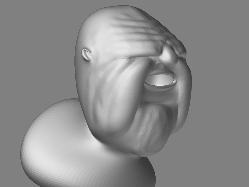
For the Normal map reload your model, go to subD5 and create the normal map. Use Adaptive and the same resolution as for the Displacement map. This will be exported to the Texture pallete. Make this into an Alpha and then repeat the steps of creating a negative and positive map.

Now in Mtor, you’ve got four maps to play with. Use a Combine template and use ‘-’ for the negative maps and ‘+’ for the positive maps. You’ll have to play around with the strength values, but this is so much easier than having to constantly rerender the maps in Zbrush with different intensity and mid-value settings trying to find the right values. For my model, I found 1.00 for the Displacement maps and 0.060 for the Normal maps worked well.

Important, when setting up the tif files within the combine template. Remember to add a ‘-float’ inside the txmake command, these maps have a much higher than normal bit depth.
Also, I found I had to set my S,T filtering values to be really low - 0.08. I think this might be because I used Zbrush’s AUV uvmapping which creates a large number of small disjointed uvtiles. Higher filtering values will start to blur the edges between each uv tile and this will introduce artifacts onto the surface of the mesh.

Goodluck, I hope this helps and I’ll post more as I experiment further.

SJ64

Hi SJ64!

Thanks for sharing that workflow! I myself have started trying to use renderman and the speed with which it renders displacements is astounding! I am going to have to try your technique.

Thanks again!

Scott

Okay, here’s the head I’ve been working on, getting this workflow sorted out.

Update: I listed a strength of 1.00 for the displacement maps. I actually needed 2.30 to get the amount that I needed. -This is from using an ‘Average RGB’ in the Imagefile settings for these maps.

Here’s the head as polygons.
ThugHead_Poly.jpg

Attachments

ThugHead_SUBD.jpg

ThugHead_Zbrush.jpg

ThugHead_Detailed.jpg

Here’s my final head. With a texture painted in Zbrush.
I have to give credit to my partner, she’s a beauty therapist and helped me with the skin tone on this head. The great thing was - she doesn’t use computers. But I gave her my Wacom and spent 5-10 minutes explaining Projection Master and how to rotate/move the head. After that I couldn’t get her off it! :slight_smile:

ThugHead_Final.jpg

great post!
I’m using a different method for resolving the problem of the displacemnt values.
I’ve modified the SimpleDisplacemnt slim shader so thar the 0.5 value is the point with displacemnt, values > 0.5 are the bumps and < 0.5 are the holes.
In this way I just flip the displacemnt map and render :wink:

gollum26, that’s a great little modification to the Slim shader. That would really save some time - having to apply the +ve and -ve alpha adjustments is one of the lengthiest parts in the process.
Would you be able to show me how you modified the Slim Displacement shader? I briefly looked at the RSL code for it, but didn’t understand enough to work it out for myself.

'regards
SJ64

the modification is really simple, but it works perfectly. I past the code of the Simple slim shader. I’ve done other modification, so I will post just the segment that interests you.
I suggest you to create another shader, 'cause if you modify directly the base slim all the previous works that use it will have modfied displacemnts.
If you don’t know how to do it, tell me :wink:

from $RATTREE\lib\slim\displacemnts.slim

RSLMain {
 		output "normal Nf;"
 		output "point PP = transform(\"shader\", P);"
 		generate
 		output "Nf = normalize( ntransform(\"shader\", N) );"
 		output "PP += [getvar Kb] * ([getvar Displacement]-0.5) *Nf;"
 		output "PP = transform(\"shader\", \"current\", PP);"
 		output "if([getvar UseShadingNormals] != 0) { "
 		output "	normal deltaN = normalize(N) - normalize(Ng);"
 		output "	N = normalize(calculatenormal(PP)) + deltaN;"
 		output "} else {"
 		output "	N = calculatenormal(PP);"
 		output "}"
 		output "if([getvar DoDisplacement] != 0)"
 		output "	P = PP;"
 

hi gollum,

I grabbed your code and loaded it into mtor, but the slim template is exactly the same. (makes sense, since your code is just the rsl Main fuction) Soo… what exactly are you doing differently with your shader and do we need any extra parameters in order to use it?

Care to enlighten us?

I helping on the shading for Scott Spencer’s Rhino:

http://www.zbrushcentral.com/zbc/showthread.php?t=025799

We might want to use your code.

Thanks,

Will Atkin

well, it’s very similar but if you notice this line in the base shader is different:

output “PP += [getvar Kb] * ([getvar Displacement]- 0.5 ) * Nf;”

That number has the obvious aim to riarrange the displacement values in a lower scale, so that when the map has a 0.5 grey value prman does not change the geometry. When instead we have lower values it moves the surface’s points inward, while if they are higher moves them forward.
I really don’t think that your base slim shader has that “-0.5” inside the rsl code. If it so, you might have a different version of the shader from the one I own.
Which version of rat and prman do you have? Mine is prman 11.5.3 and rat 6.0.1

Hi gollum,

Ah I see what you are doing now, just adjusting the midpoint value. I had used a remap node to achieve the same thing.

As far as version i’m using pro server 12.0 and RAT 6.01.

thanks for the reply. i still might try out your shader!

Will

Just to show how this simple trick works:

[hand.jpg](javascript:zb_insimg(‘11490’,‘hand.jpg’,1,0))

The displace is quite perfect and it doesn’t show differences from the zbrush model, except for that lines on the nails… but I think they can be easily avoided making the disp “Adaptive” or incresing the subpix resolution (in the picture is 0).

Nice hand.
Nice Render of said hand too! :wink:

SJ64

hi gollum,

i follow your tutorial and i read that you mention to create on ealpha for negativeDisplacement, one for Positive displacement and one for normal map,

but how do you apply normal map in renderman?

Interesting Reading:

Has anyone figured out a workflow for Renderman for Maya yet? It sounds pretty simple: it apparently uses maya’s default displacement node, sub-D surfaces, and you just need to adjust the tesselation on the shading group? I 've heard it can even do 32-bit displacement.

Anybody using it or know anything concrete?

Zbrush to Renderman pipeline

-Import model into zbrush.
-Save it as a morph target.
-Subdivide mesh.
-Do your thing(model).
-go back to the lowest subdivision model.
-switch morp target
-Make displacemet map
-Make sure you dont use adaptive mode.
-Turn on dPsubpix to the highest.(this make take a while).
-Export d map
-When using renderman use a conbine displacemt map.
-set base to -.50.

  • add a bump map
    -add an image file to it.
    -in that image plane do te follow
    -the gain you have to set it up to whatever the alpha depth factor was in zbrush
    • then render
  • it may not look the same because there is some gama diference
  • set the gama in render man lower and play with it until you get the resutl you want
    -this setting is in the same image file
  • it is call bias. set it at 0.43 for a start
  • if it does not work for u set it lower.
    I will apreciate any feed back

colombiang3 wrote:

Thanks for the reply. I’m just not really clear on what you were explaining. I was asking about the Renderman for Maya plugin, specifically. I’m confused if your describing a straight renderman workflow, a Mayaman , or a RAT workflow?

But since you responded I do have a couple of questions:

  1. You said use dPsubpix at its highest level, rather than Adaptive. Are you doing this to generate really fine, ie. pore level details?

Thanks, in advance.