I’ve been working as a medical technician for a little over a year now. Our lab focuses on digitally planning facial reconstruction surgeries using CT scans and a variety of software packages. We then utilize 3D printing to create life size models of the planned surgeries. We have been using the Freeform Haptic feedback arms for the majority of surgical planning, but with the new advances in zbrush I think soon in the future it could completely replace an entire suite of expensive 3d medical applications for a fraction of the cost.
Also i think if zbrush could somehow get a plugin to create and edit models from dicom images using masking and region growing it would be crazy awesome.
I thought I would share some of the models I’ve been working on that zbrush has really helped me do quickly and to a much higher quality than anything else would allow me to do.
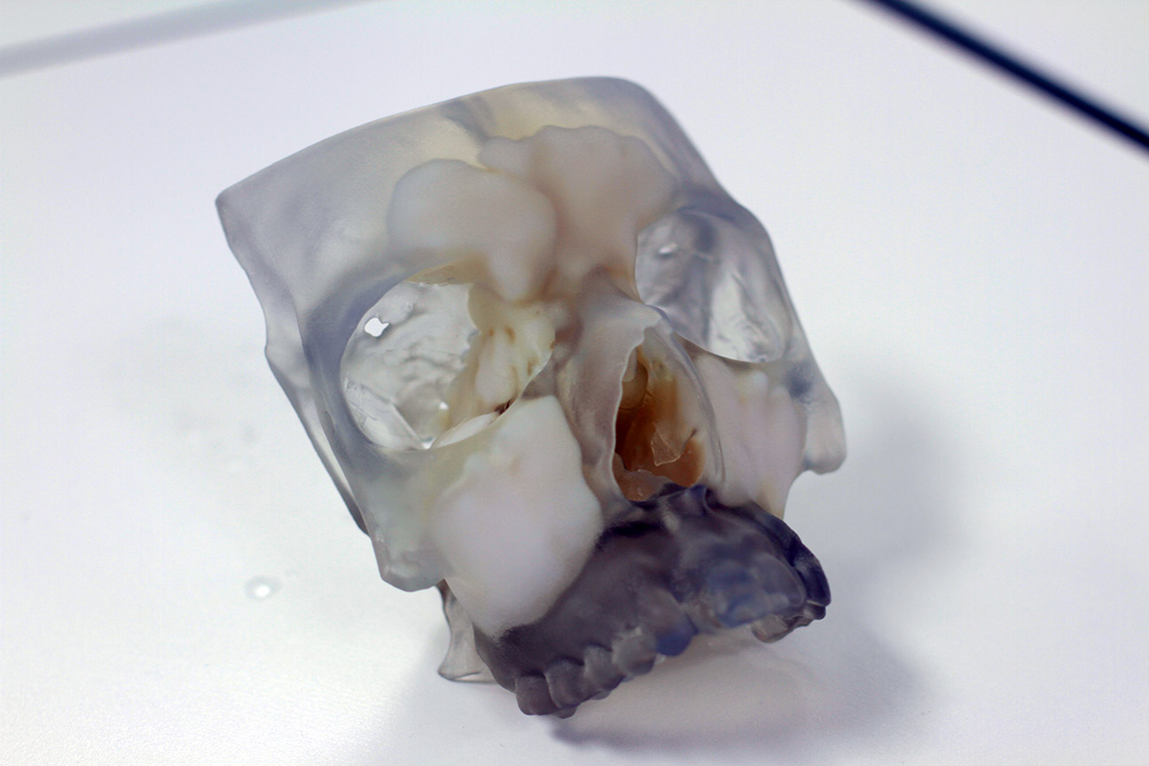
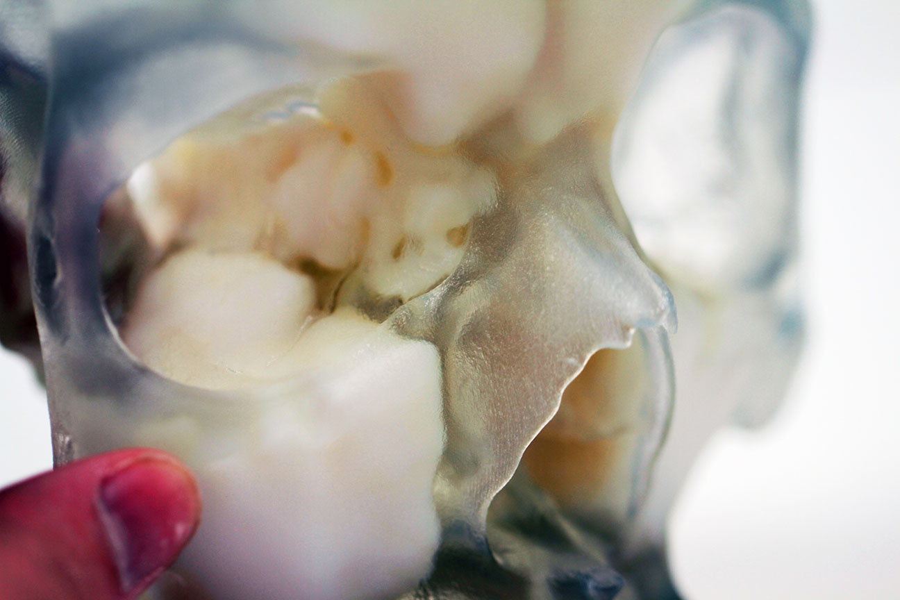
this is a 3d printed skull of a colleague where he wanted to show all of the sinuses to his students so that it could be more easily understood where they are located in the skull. The models where based off CT scans but using dynamesh, polishing, smoothing, and decimation master i was able to clean up and have a much smoother and higher detail mesh than the original data gave me.
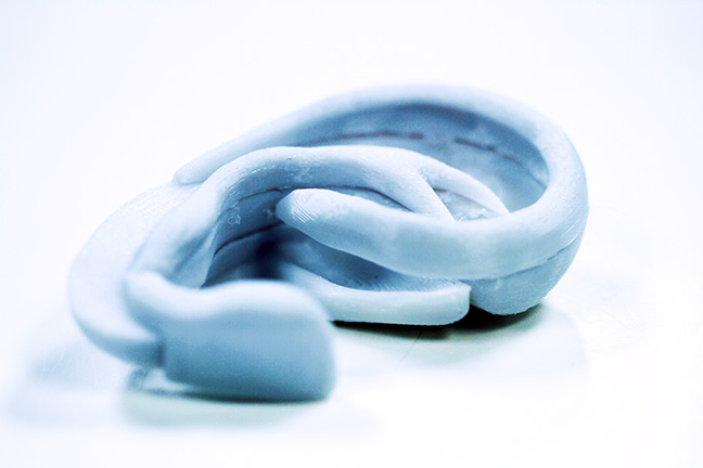
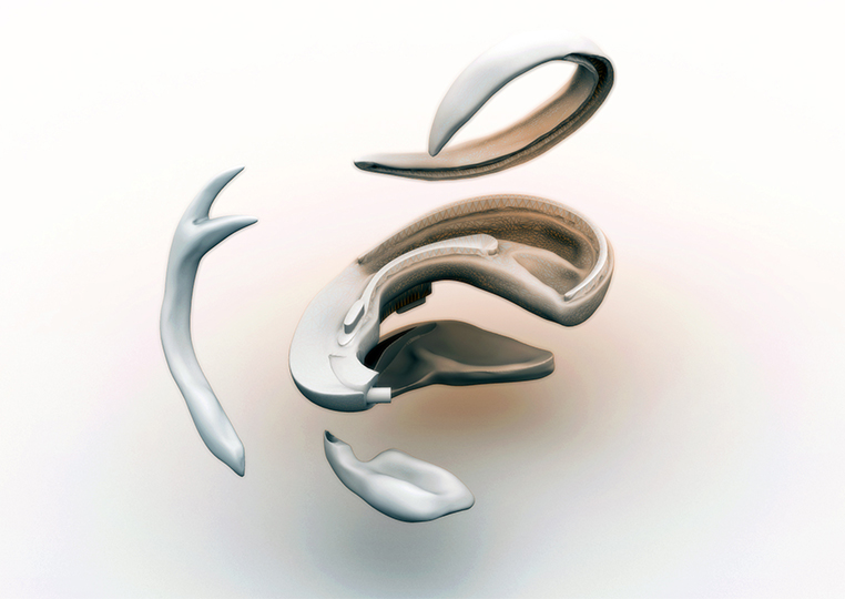
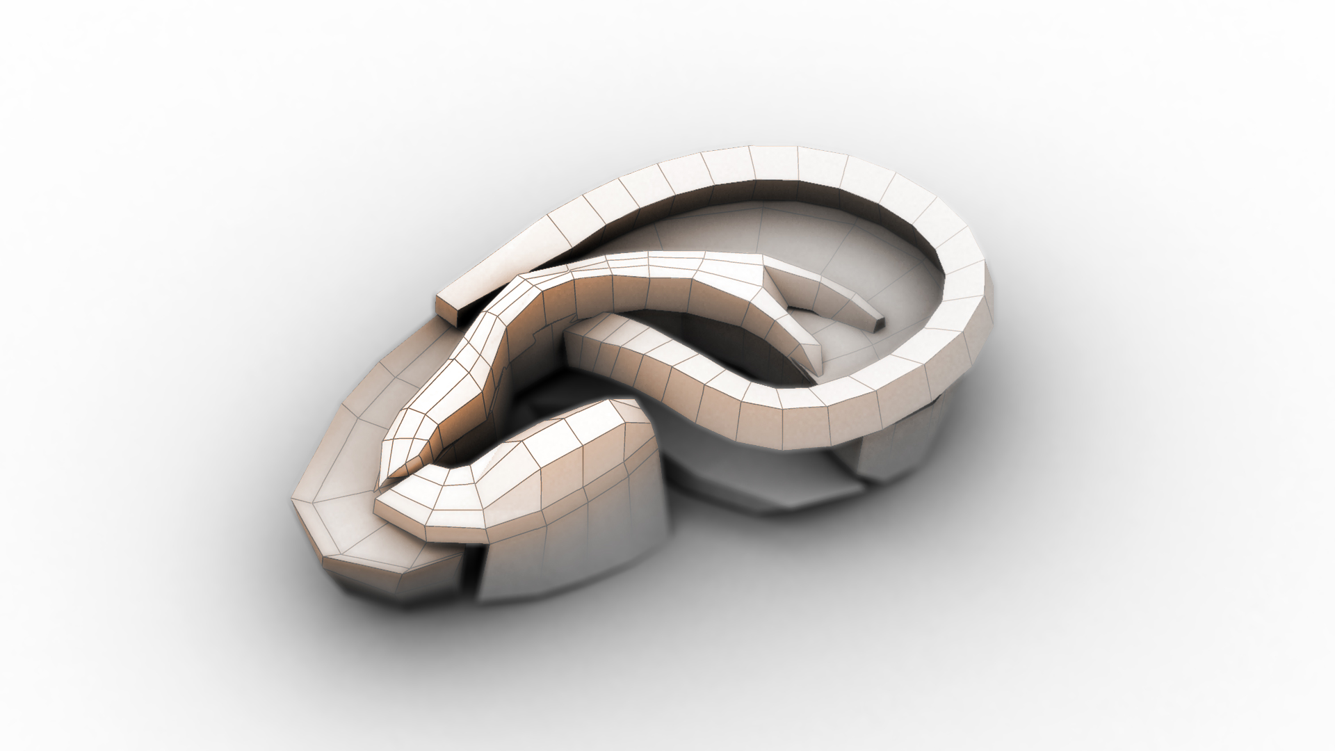
This was a project to create a model of human ear cartilage that could be used in surgery as a reference when carving rib cartilage. All the pieces are printed separately in poly-carbonate plastic and then can be assembled together. I did this back before dynamesh existed so i spent alot of time doing re-topolgy, if I had to do this model now i could do it in a fraction of the time.
more to come but cant attach more images in this post.
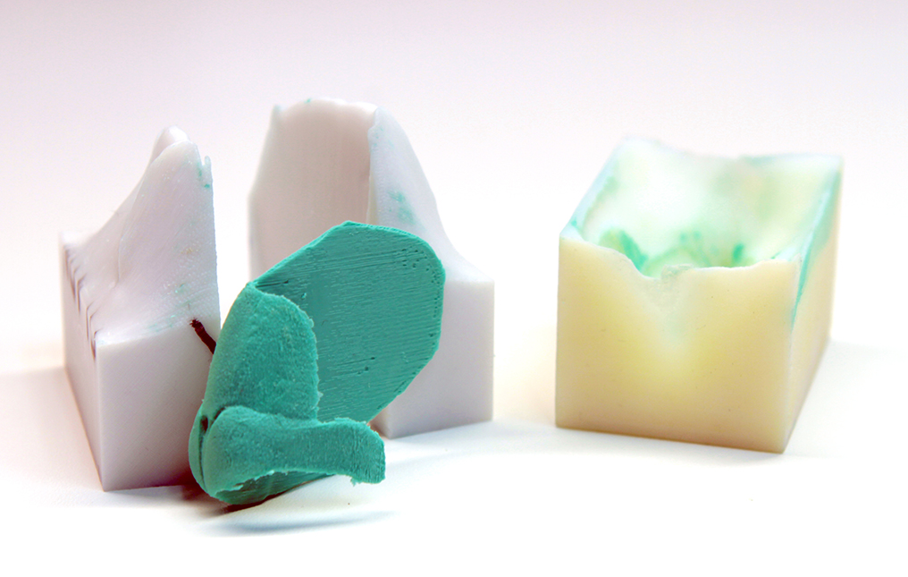
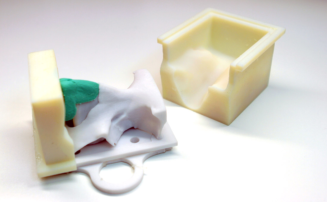
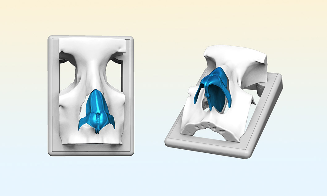
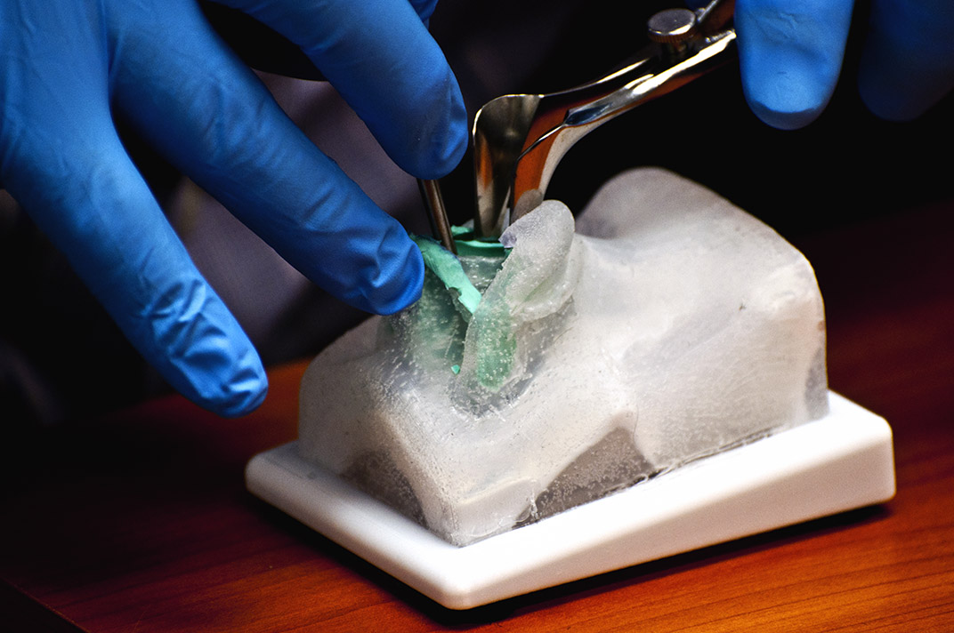
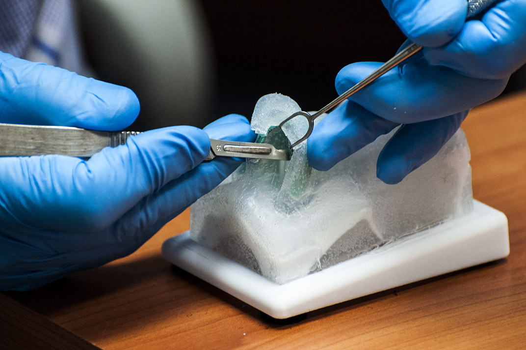
this is another project creating a rhinoplasty surgery training model. It was initially based off of a CT scan, so the skin and skull were derived from that. I modeled the cartilage using box modelling techniques and a lot of back and forth between maya and zbrush. I collected all of the model parts together in rhino so I had one scene with everything at a set scale. Initially figuring out how to cut the mold lines was quite a headache but I’ve perfected a technique just using a plane in zbrush and then building extruding a boolean shape from it that makes it extremely simple to make complex molds very quickly. The cartilage is cast in a silicone with a durometer of about 50, and the skin is a different silicone with a durometer of about 5 so much softer. You can see all the steps (Simplified of course) on my coroflot here: http://www.coroflot.com/JDS/Rhinoplasty-Training-Module
the molds are all re-usable but the skull is a one off 3d print. in the process of being used the model is destroyed because the surgery requires breaking the bone around the nose.
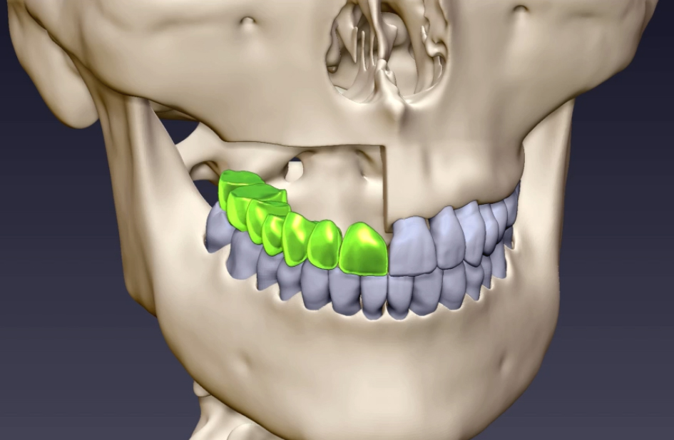
I also did some ztimeline animations. I had a really short amount of time in order to do these so animating them in zbrush made it really easy. these show a rough overview of how several different facial reconstruction surgeries happen. The skull was originally a CT scan, but I sculpted all of the teeth and other components from scratch.
If someone can point me to a guide on how to attach videos directly in the post i would appreciate it, but for now here are links to the videos.
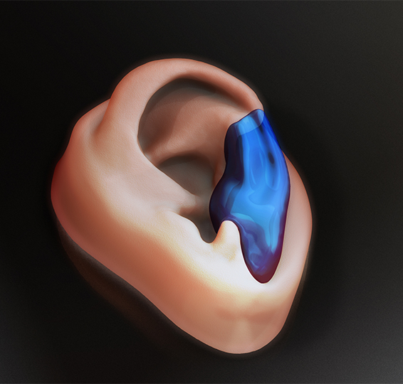
heres another render showing an ear reconstruction. The blue part is the desired skin position. That piece is then offset to the inside by a mm or 2 to get the shape for a cartilage insert.
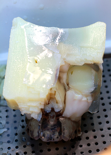
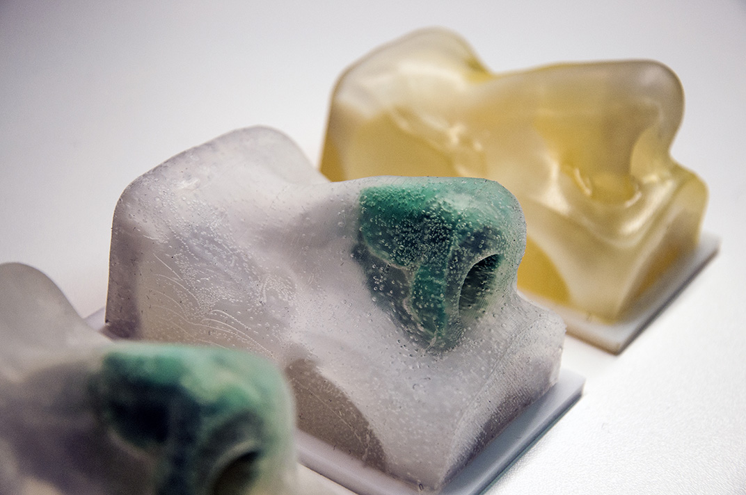
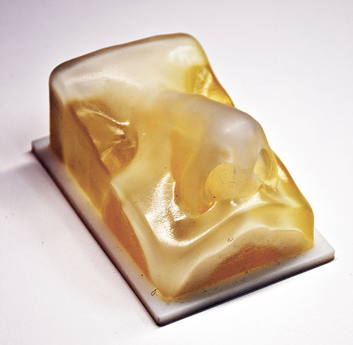
oh and a digital material print from the objet. This was all printed as one part using 2 different materials. The yellowish material is a soft rubber like material - sadly its durometer (hadness) is too large so it doesn’t work that great for mimicking skin. Its hard to see but it actually has a cartilage piece printed inside at the correct durometer by mixing the hard white material and the rubber like material together.
Nice stuff! Looks like you’re doing some work that does some real good. For people who have had an accident, facial reconstruction can be a life saver.
Yes cleaning up CT scans is not as simple as it sounds for sure. A lot of the time there is scatter, especially if someone has fillings in their teeth. sometimes alot of guesswork is involved in masking out the correct areas because the scan has so much blown out scatter, almost like trying to edit a photograph that was overexposed, you aren’t getting any of the detail around those blown out whites back.
My mold line process is very simple, before I thought of doing it this way I was trying to do the same thing in much more complicated ways like projecting curves in other software. The process is essentially using a boolean to cut off one half of the mold, then flipping it to get the other. You can do this simply in CAD programs if you have a mold line that can be cut through one axis (eg a 2 dimensional line/curve). Zbrush’s slice curve also does this extremely well and very quickly. But if your desired mold line does not fit on a flat plane, like it will for most organic shapes you need a 3 dimensional mold line. I started out doing this in maya, but in zbrush with a tablet you can move everything into place much quicker. I also tried using masking out parts I wanted to seperate into molds in zbrush and was eventually able to create some molds but found it was much more labour intensive than the process below.
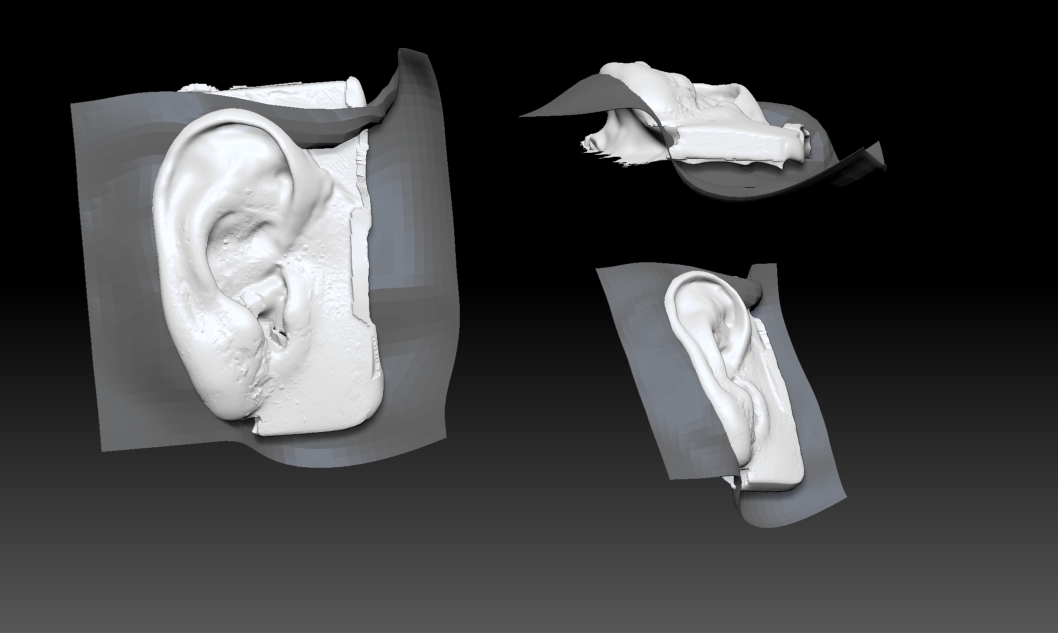
here is an image of a part line plane I setup for an ear in about 2 minutes just to help get the idea across. I would tweak this plane until I was happy with where the plane intersects with my part. Then if the plane is very high resolution I decimate it and export or goz to maya where I then select all the faces and extrude outwards so that it encompasses the entire part. Then you can bring that back into zbrush and boolean away the extruded box to get the first half of your mold. You could also boolean in any other program with that capability. Sometimes I will use Rhino instead because it does not modify the geometry of the part when you boolean - whereas zbrush’s boolean uses dynamesh or remeshing at the moment so the entire mesh is recalculated when you boolean, if I need to be very accurate this is not the most desirable. At high dynamesh resolutions though I find it is still fairly reliable, although there is still sometimes some cleanup required and you need a fast computer or you will be waiting a long time.
hope that helps let me know if it needs more clarification.
extremely interesting post, thanks very much for sharing - its interesting to see the worlds of radiology collide with the cg world. I’m not very familiar with the subject, but from dicom files you mostly get point clouds, or triangulated point clouds i guess? you can clean those up efficiently in meshlab, or similar opensource apps before bringing them to zbrush.
There are different ways of dealing with the data, but essentially the value of each pixel is representative of a hounsfield unit - a measurement of density. This data than then be taken into software and constructed into a 3 dimensional array or voxels. So you could probably generate point clouds, and then make a triangulated mesh from that data.
Right now we use a program called mimics that loads in all of the dicom image series data and then allows us to do a bunch of operations on the voxel data set it creates - the most important being the ability to select areas of interest by manually masking things in or out layer by layer. Most of the time the cleanup needs to be done in the actual voxel editing stage because the meshes generated are for the most part very ‘clean’. Although in mimics at least you are limited to editing from orthogonal views so some editing steps can be done much quicker after the fact in something like zbrush.
One of the biggest hurdles before was actually that you couldn’t get an .stl into zbrush. That is the standard format that most medical modelling applications use, so If I wanted to use zbrush on a mesh I would have to spend half an hour importing a million polygon or more mesh into rhino/maya/max and then try to export an obj. Now with the 3d print exporter I can just import it directly in a couple seconds.
The other thing that made things difficult was before dynamesh was introduced - it would basically be impossible to edit these giant meshes using manual retopology.
We currently use freeform for most of our model editing - this is the software that comes with those haptic feedback arms. It essentially imports any mesh and then turns it into voxels. I would say it is pretty close to working with dynamesh. It works pretty good for most tasks, but i’ve done accuracy comparison tests between meshes from freeform with different resolution settings, and zbrush with different dynamesh resolution settings with and without reprojection and zbrush was a clear victor at maintaining a closer accuracy to the reference mesh.
thanks for the detailed description of the process! I actually use OsiriX on osx to view dicom files, or maybe photoshop on windows, with the 3d capabilities its ok for viewing on a basic level. From an artistic point of view I think we can learn so much from these, i hope with the all the new technology the specific scientific disciplines get closer to each other, maybe even overlap a bit. I think each can profit a lot from the knowledge of the other. Now they are kinda sealed up, so its refreshing to see such posts as yours - radilogy, ct and mri gives us a the best understanding of anatomy, and its good to see examples of surgical or dental modeling here, which is in very serious form of art, in my eyes. i definitely keep an eye on this thread.
hi
fantastic work, i really like the rhinoplasty training tool, im sure its really popular with surgeons, is it something you have put in production?
I also really like the model showing the sinuses, did you have to inject the spaces or something?
Is it difficult to remove the supports after printing?
matt
Looks like most (if not all) the models are done on Objet machines. The support comes off very easily with a basic pressure washer water system.
I thought Mimics had an obj exporter, but I could be wrong it’s been a while since I was looking into it. This stuff is very hard to deal with in Zbrush, that was until dynamesh and qremesher. It’s made things like this incredibly easier to deal with. I’m not sure if Zbrush will ever implement direct Dicom files (they can vary greatly from different machines) as it’s more voxel based and deals with things like density and point clouds. Also with things like this scale and sizing is extremely important and could even be the difference between life and death.
Great stuff and it’s great to see Zbrush progress more into this area of 3D.
Once we get the CT data in it is all precise measurements. However “garbage in garbage out” If your slice thickness is too large the data will not be of very high quality. Although you can kind of fake it with smoothing and polishing, its always better to have higher quality input. Normally the largest slice thickness (From the scan) that we accept is 1mm.
Thanks. We are working on getting it into production. The project was original started as and Industrial Design colleague of mines graduate thesis. I was then given the task of taking his prototype and trying to make the hold much more production friendly. It is still a laborious process to make the model because the silicone is poured by hand, but it is much simpler to make small runs of the model. The surgeon I worked with on this project wants to be able to give them to his residents so that they can learn how to operate on the model before even seeing a patient.
The sinus model was made by taking the CT data and then thresholding it first to get a model of the skull, Then a different threshold was used to select the cavities - the masking generated by this threshold then required alot of manual manipulation. Once you have an stl of both the skull and the sinus you can simply print them both together, this one was built on a Objet Connex 260 with the Vero White and Clear materials.
It depends on the models geometry. For the skull it is not too bad, although getting into some of the small crevices can be fairly labour intensive. One model I was working on took hours to remove the support because it had some very thin internal channels.
Yep you’re right. Our lab has an Objet Connex 260, and an Objet Desktop 30. We also have a Thermojet wax printer, A fortus FDM printing in Polycarbonate plastic, and a Dimension FDM printing in ABS plastic. The rhinoplasty skull model is printed in Polycarbonate, and generally the molds are too since they are very rugged and can be re-used many times. If I want a nice finish on my mold I’ll use one of the objet machines because they can recreate much smaller details like skin pores etc, although they don’t seem to survive as many mould pours.
For the objets support is removed fairly easily using the water jet in the cabinet like you described. For the PC printer all the support has to be removed manually by hand, this means that complex parts like skulls aren’t the best candidate to print on it, but things like molds or things you would consider ‘parts’ work really well. The ABS machine has dissolvable supports so we can throw them into a tank of lye and leave it for a day and all the support will be gone.
I’ll look into it again but I’ve never been able to find a way to export obj from mimics, but that would save a lot of time. May be a plugin I could get somewhere. I definitly agree, before dynamesh zbrush really wouldn’t have been a consideration, but that alone opens up so many doors. Scaling is definitly another issue I have had to deal with when using zbrush. most of these other programs default to mm or inches and you can feel pretty safe about your scale staying correct. When working with zbrush I still feel a little iffy if my scale is going to stay the same or not it sometimes seems to shrink or enlarge my models and I’m not sure why.
I know I’m not sure it makes sense for zbrush to move into dicom manipulation but I can dream… I think the tools that zbrush already uses like masking and polygroups could make it a really enjoyable process to get a model out of a dicom sequence.