Hey this is a fun setup!
I am not up to date with any of the mr lenses…
- how far should you Camera be from the subject?
- Are you using any Shadow settings on the light?
Thanks!
Hey this is a fun setup!
I am not up to date with any of the mr lenses…
@Aberrant: chromatic aberration is a type of lens distortion where the lens fails to focus all colors to the same convergence point. It’s usually most apparent toward the outer edges of the frame. Bokeh is more of a blurring phenomenon. Neil Blevins has a good article on bokeh. You can actually make your own custom bokeh maps to use with that lens shader, so you could make it circular, octagon, or even some really strange shape if you want 
@ sadicus - The Plane of the Bokeh lens defines the focus distance (in maya units), you can use a measure tool to define that value.
@ dustinbrown - The mr bokeh lens with the proper image simulates chromatic aberration and bokeh 
Awesome tutorial! I’m having a few problems, though. I’m getting a black render in one camera and my model isn’t showing in another. (Warning: (Mayatomr.Scene) : GiantZBrushPolyMesh3DShape: empty UV set map1 detected, ignored). I’m using a decimated mesh, but I haven’t had a problem in the past.
Do you think you can post the lighting rig so I can see where I went wrong?
Thank you dustinbrown and ISK-86 for the replies.
The Neil Blevins description is a great example Dustin.
The image is pretty much an alpha for the shape of the Bokeh effect from what I understand.
@ ISK-86: If the MR lens shader simulates both Bokeh and Chromatic Aberration, what is the use of the image file?
What I mean is, what if you turned the blades to a value of 5. That would give a pentagonal Bokeh as well correct? And the Chromatic Aberration should be calculated as a part of the shader right? Or is that the reason you used the image, to force the chromatic aberration?
Also, instead of measuring and typing in a value for the plane attribute, could you link its distance to the camera aim node if you needed to animate the camera?
Lastly, the radius controls the blurriness or amount of de-focus, but is there a way to scale the effect? As in actually scale the size of the artifacts? Or would this too be tied to the image, and decreasing / increasing the size of the pentagon?
thanks a lot for this. gotta try it out.
-r
thanks for this! im not good with lighting and rendering so this is quite useful for me cheers 
@ KillahPriest: Make sure that the CM2 Factor is 10,000 else you’re letting no light in, the Empty Uv set warning is because the model has no uv information, that should’t be a great issue though. Try to layout uv’s with Uv master and generate the proper maps… I’ll upload a tutorial soon for this process.
@ Aberrant: The use of the image is to describe MR how the bokeh should look. The shader has some info for the -normal- bokehs, pentagons, hexagons, circles… but no chromatic aberration. With the image you can make any bokeh silouhette that you want (crosses, squares, hearts…), overriding the blade count and angle.
The Radius parameter makes that effect bigger, while de-focusing those. (You’ll need more rendering time for that). So, they are tied together (bokeh size & defocus)
@ Rasmus & Phorst: Thanks guys
First of all… the bottom row image :lol:
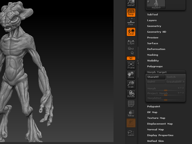
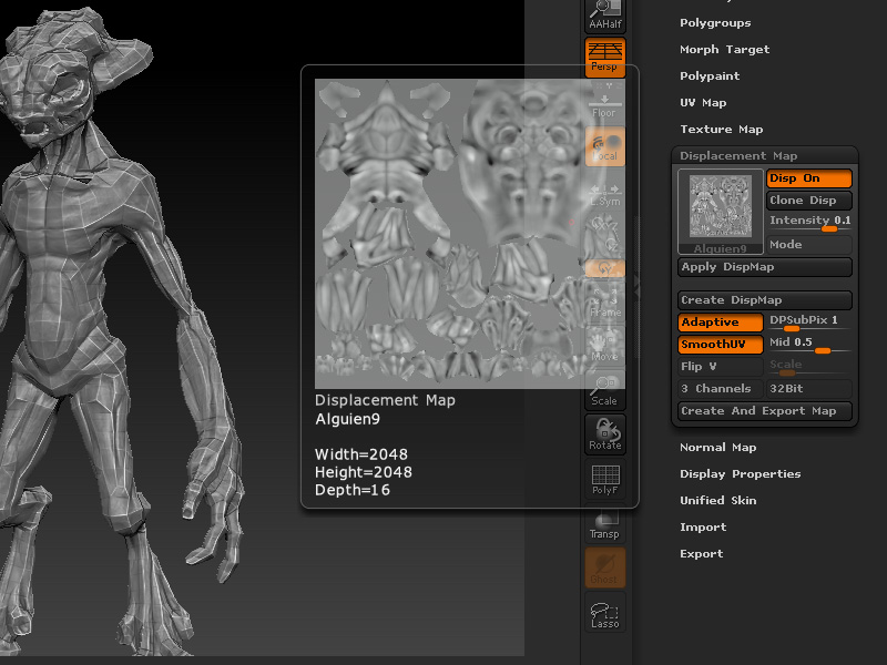
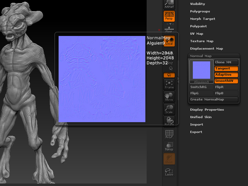
When rendering, mental ray will subdivide 3 times the mesh and generate the displacement, then it will apply the normal maps. If the normal map is generated from the lowest subd level, the result is
Full displacement map detail + Full normal map detail = The double of detail needed.
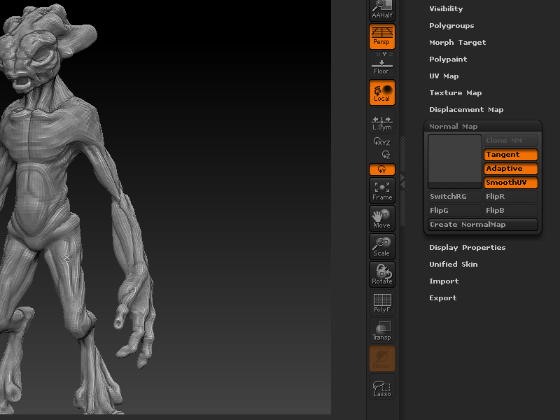
With this milky normal map the result is
Full displacement map detail + Normal map complementing detail = Just the amount of detail needed.
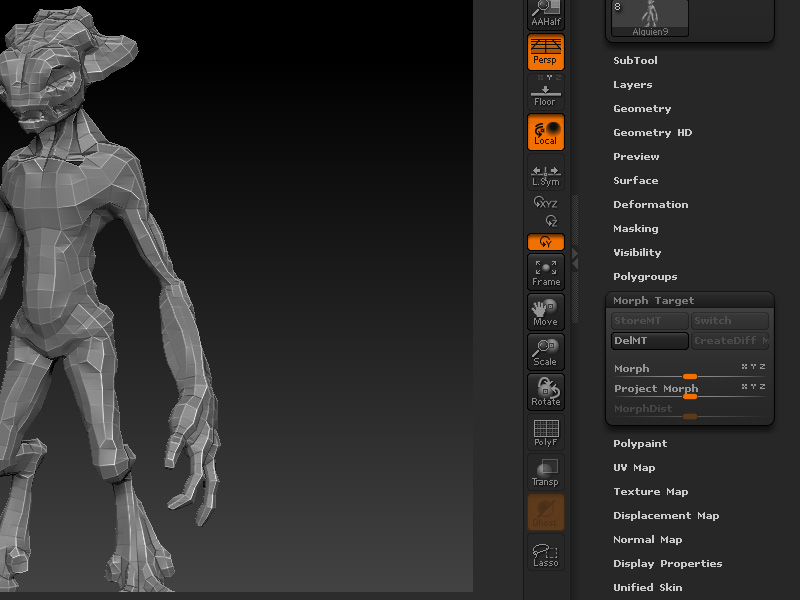
The last thing to do is export the lowest working subd level (in my case, 1) in mb format, open it in maya and have fun rendering
Thanks ISK-86 so the image is to force the chromatic aberration, and if you want more you must edit the original image to fit. Thank you for explaining, that is exactly what I was looking for. Very helpful!
That’s a really great tutorial, very useful and the end result looks really realistic (and the model is really cool too). I’m will try that with one of my model this weekend, thanks for taking time to help others!
5 stars for this awesome tutorial 
Great overview, thanks for sharing your workflow
thanks so much for sharing this, I’m finding it very usefull
awesome! cud u please post the render result in maya from the .ma in tutorial 2?
I’m still having trouble getting a result similar to yours. Everything seems washed out. I didn’t realize how big a part scale played with the physical light.
That’s great~Learning~
@ Aberrant - That’s right, thoug Bokeh shader is great for the effect, using it with the image gives you a little extra 
@ MightyReg - Thanks! Hope you can upload here that render
@ Super Glitcher, enochian, and 99530869 - Thanks for the feedback guys, always a pleasure to help
@ Killah - The maya’s color swatches are a little messy when gamma is involved in rendering (the 2.2 gamma in the lens), just make the colors a little darker. If you are using a diffuse texture from zBrush you’ll have to plug a gamma correction node between the texture and the material, with a gamma correction value of 0.455
@ Phrost - Here is the raw result, just duplicated and rotated the mesh…

Great tutorial!
If you don’t mind could you give a more in depth explanation of how you export as a .ma file so you don’t have to go through the typical hassle.
I am attempting that method right now but I am having some problems with the displacement maps coming out right.
Very helpful. I’m just adding another ‘thank you’ to this thread
A few more specific quuestions for ya.
I’ve been messing around with the mia_material. I’d like to know where to plug in the tangent normal map and how to do that, where a color specular/or reflection map would go, what setting controls the amount of gloss and size, so I can hook up a gloss map,
Lighting intensity and decay rate for the area light attribut settings would be nice. Or do you use suppress shaders to have the phsycial light take care of that? Which opens up some new settings which I’m not familar with, Cone, THreshold and Cosine Exponent. These also don’t seem to update in the real time views.
Planar=distance from camera, that solved a huge problem I had. Is there a way of seeing a visual indicator of where the DOF is exactly?