ZBrushCentral

Isaac Oster - Sketchbook (breakdown Pg. 10)

I wanted to try out some of the new features from R4, like IMM and fiber mesh. I also needed to expand my portfolio to include some fantasy type stuff. Anyway, chose a horse and rider. If you have suggestions, I’d love to hear them. I’ll be starting on the low poly in the next day or two. Thanks for checking it out!

rider_47.jpg

rider_48.jpg

Attachments

rider_47.jpg

rider_48.jpg

Really nice work! I really like this last one. Are you going to push it more or move on to textures??

This is REALLY good!

More!

:+1:small_orange_diamond:+1:

Great work, i like! :wink:

Clean and professional, good stuff )) :+1: Looking forward to seeing the low-poly version

Thanks, hey Nick! I got some pretty good pointers on where the horse anatomy could be better from Brian, as well as some notes on the cloth, so I have a bit further to go. I’d love to hear suggestions of how I can take this further.

Based on this concept from Darren Bartley.

colors_front_02.jpg

colors_side_02.jpg

colors_back_02.jpg

Attachments

colors_back_02.jpg

colors_front_02.jpg

colors_side_02.jpg

Very nice work, bravo! :smiley:

Cheers, David

Amazing work!! great thread btw:+1:small_orange_diamond:+1:small_orange_diamond:+1:

wow, awesome sculpt!

swat_02_final_10.jpg

swat_02_final_11.jpg

BMTA_final_07.jpg

BMTA_final_08.jpg

Attachments

swat_02_final_10.jpg

swat_02_final_11.jpg

BMTA_final_07.jpg

BMTA_final_08.jpg

woow man clean models and textures
congrats

When did you do that hard surface alien? Why have I never seen this?

Hi,

I was re-viewing your entire thread tonight and want to thank you for taking the time, first to show your works and works-in-progress. I enjoy looking at the depth and breadth of your art. And I also want to thank you for going through and taking the time, in great detail to breakdown your processes. Much appreciated!

This is based on Darren Bartley’s amazing concept. I posted an earlier version, but came back to it for a proper paintover. Some notes about the process are available on my website.

mech_girl_01.jpg

mech_girl_02.jpg

Attachments

mech_girl_01.jpg

mech_girl_02.jpg

1 Like

Awesome!

Beautiful hard surface work! You should share more information about your ZBrush techniques and exactly where ZBrush was used on this project. :slight_smile:

This is based on Darren Bartley’s amazing Fembot Concept.

Here are a few shots and a bit of information about my process. I start by modeling the head, and add paneling and replace existing geo using retopology and creasing. This is my go-to process for a lot of modeling, hard surface or not. Use whatever initial geometry you want, sculpt it into a scaffolding to support clean, low poly retopology. The scaffold geo doesn’t have to be perfect, it just has to have geo where you want to retopologize. When you create your preview mesh, give it a little skin thickness, and viola. Crease the edges that need creasing, and move on.

To start the head, I’ll usually just create simple tube from 3 zspheres. Using move, dam_standard, and flatten (4r4), I get the head shape roughed in. It’s really hard to get the eye lids, lips, and other fine detail sculpted without doing a quick retopology of the mesh. The mesh 2nd from the left is retopologized.
head_progress_01.jpg

Once the base head is done, I start adding the first panel. As I mentioned above, I need geometry to use as a scaffold for retopology. To start the top piece, I appended a cylinder, positioned it in the middle of the head, and retopologized the rough shape of the panel. Once that was done, I gave it some skin thickness (essentially just an extrusion). Skin thickness lives in the topology menu, which is only available when a zsphere is selected. After previewing the mesh (the ‘a’ key), I made it a PolyMesh3D and appended the new geo to the subtool menu. To make retopology as easy as possible, I’ll usually switch to the chalk material and darken the global RGB a bit.
panel_creation.jpg

At this point, I need to crease the edges. Creasing tells Zbrush to preserve the edges for a specific number of subdivisions. It’s similar to adding a turbosmooth modifier in 3DS Max and telling it to preserve smoothing groups. There are two main parts to the crease settings to pay attention to. The first is CTolerance, aka crease tolerance. The number represents the angle two faces meet at. To be honest, I’ve never worked out exactly what the relationship is. I don’t know if its measured from the inside of the face or the outside. Functionally, the higher the number, the less sensitive it is. At 180, the default setting, it ignores all angles and only creases open edges. I use the Select Lasso to isolate each face or group of faces with edges I need to stay sharp. The default selection shape is a square, which is rarely ideal. Holding the control key + shift activates this tool. If you click on the brush menu icon while holding these keys, you open a menu with various options. I prefer the select lasso for this task. Once the correct faces are isolated, simply press the crease button. If the edges have not already been creased, they will be, and the hidden geometry will become visible again. Zbrush will crease the edges associated with the extrusion by default. The image on the lower left shows the edges I needed to preserve.

The other important setting is CreaseLvl, aka crease level. This controls how many times you can subdivide the mesh while the creases are preserved. The default setting is 15, which is a little silly. My calculations could be off, but a 6 sided cube divided 15 times yields a mesh with way over a billion faces. I find a setting at or near 3 is perfect. What happens is you divide the mesh 3 times, and the creased edges stay sharp. All uncreased edges are smoothed with each division. Once you pass the crease level, the mesh is divided and smoothed uniformly. The result is nice clean hard surface geo, without the razor sharp edges that make things look computer generated.
creasing_01.jpg

Once I had this new piece of geometry, I carved the pattern of the final piece of geo as a guide using the dam_standard brush with lazy mouse. I could have polypainted the guide lines, or just eye-balled it. Then I retopologized a new piece of geo following the guides, set up the creasing, and subdivided. Some pieces required multiple steps, and some I was able to retop directly off the head.
final_retop.jpg

Here’s another example this process. I used the original face as the scaffolding, paying close attention to where I wanted the panel edges to go. Using as little geo as possible makes it easy to move these points around once you make it into editable polygons. In this case, I needed to mask off the edges and reproject the sculpting from the organic part of the original sculpt. I continued refining it as the sculpt went on.
face_creation_01.jpg

Here are a few shots of the progress through this phase of the modeling.
progress_01.jpg

Attachments

creasing_01.jpg

face_creation_01.jpg

final_retop.jpg

head_progress_01.jpg

panel_creation.jpg

progress_01.jpg

1 Like

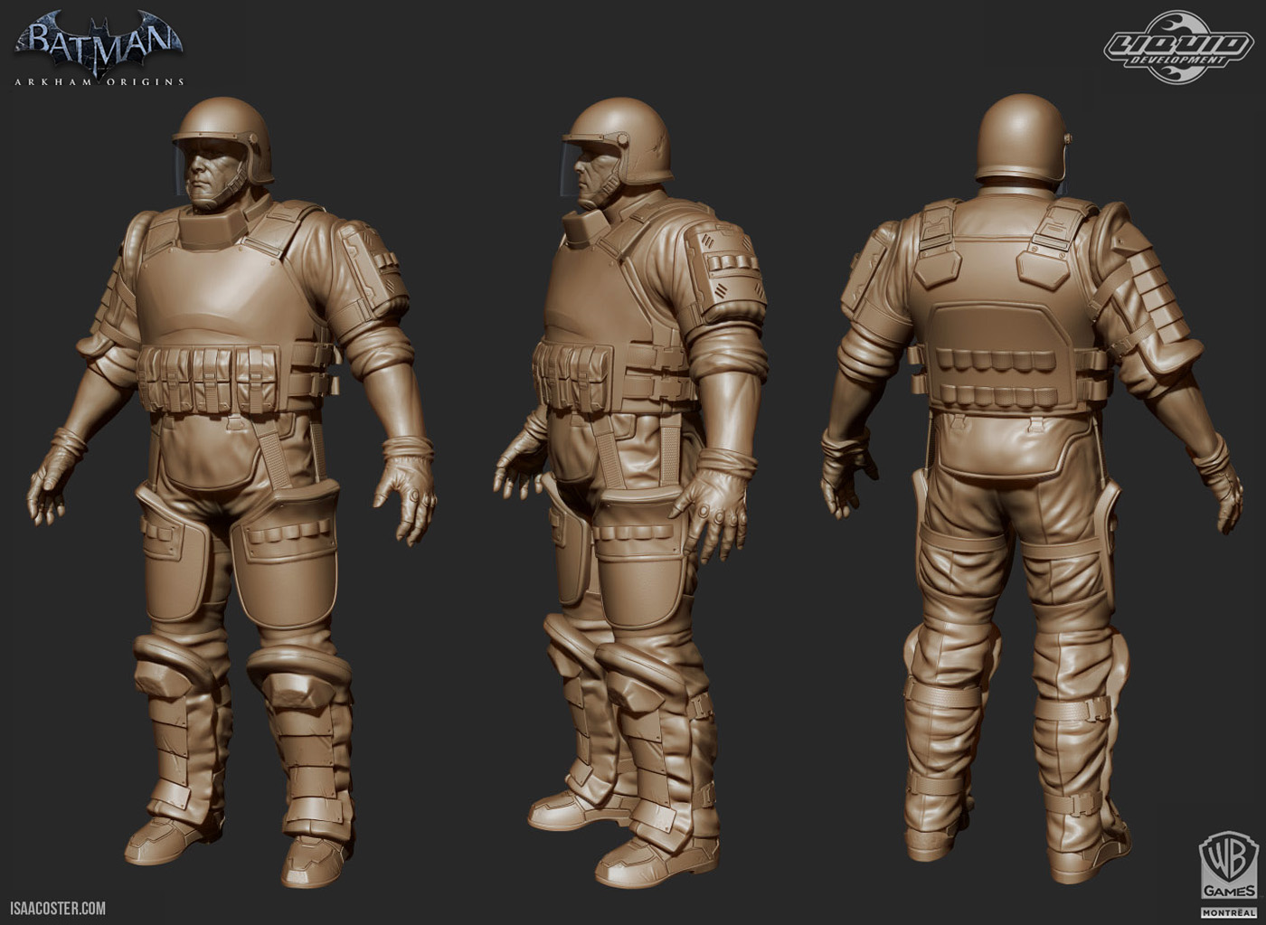
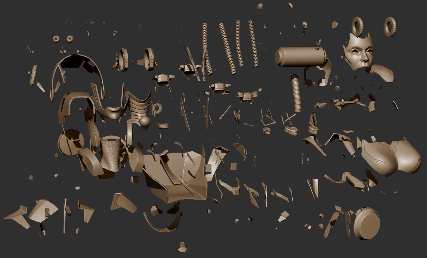
I find some geometry is easier to create in 3DS Max. Generally speaking, if something looks like it comes from a primitive, I’ll try to build it in Max. Once I have a widget, I’ll reuse it as much as possible (without overdoing it). Most of this geometry was created in Zbrush. The final subtool count is around 150 pieces.

exploded_01.jpg

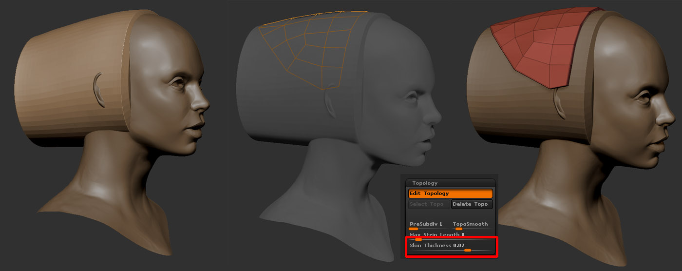
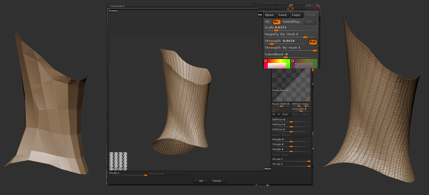
I didn’t use a whole lot of noise maker on the project, but it did come in handy for a few pieces and is definitely worth mentioning. Noisemaker lives in the surface menu. What it does is tile an alpha over a surface. You can change the scale, the intensity of the deformation, and mask the surface according to the value of the alpha texture. I wanted to make sure it wasn’t possible to see through the mesh, so I borrowed part of the neck from the original head sculpt, shrunk it down a bit, and added a tiling pattern. For the most part, I use the UV mode. This helps avoid stretching (unless your UVs are distorted). I did a quick UV unwrap using Zbrush’s UV Master plugin, grabbed a great tiling alpha from Pixologic’s Download Center, and applied it to the mesh. To apply an alpha, just click the alpha button in the lower left hand corner of the window. Be sure to activate Uv mode in the upper right hand corner of the window. For some reason, reducing the strength value actually increases it. Scaling acts like you’d expect. If you have a part of the mesh you don’t want the pattern on, you can mask it off. Leaving Strength By Mask set to 1 will completely erase the pattern from any masked geometry. One really nice time saver is the copy/paste function, if you need to apply the same pattern to multiple subtools. By default, the pattern behaves very similarly to a bump map. The geometry appears to have the detail, but the silhouette is unchanged. In the main surface menu you can apply the pattern to the mesh if you like. There are other settings to play with, and more in depth tutorials if you need more info on this tool.
noise_maker_01.jpg

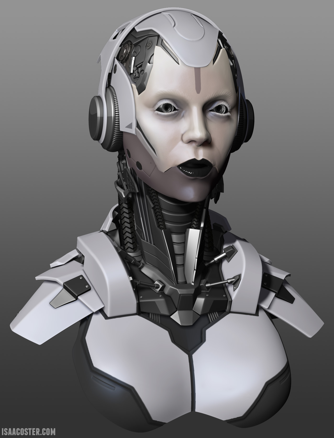
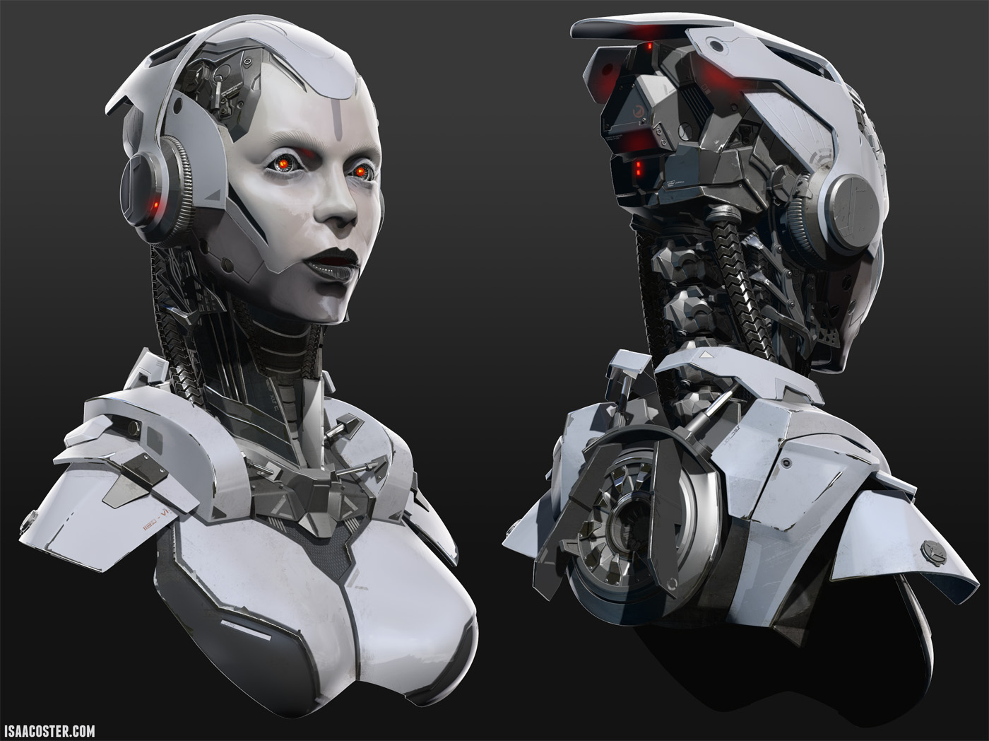
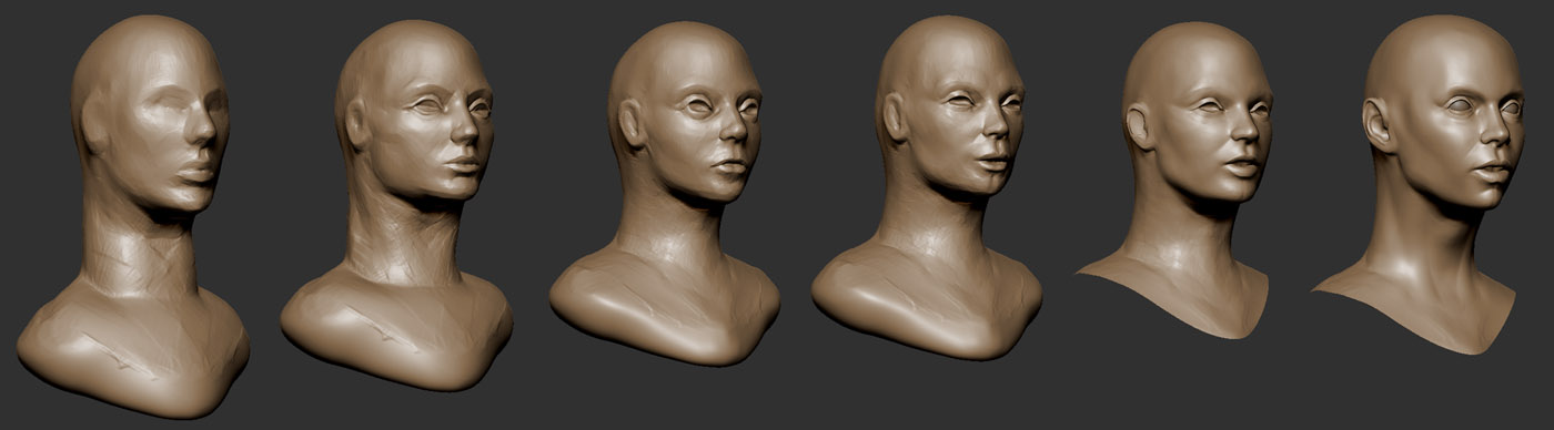
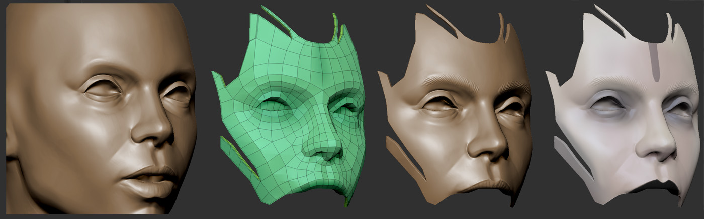
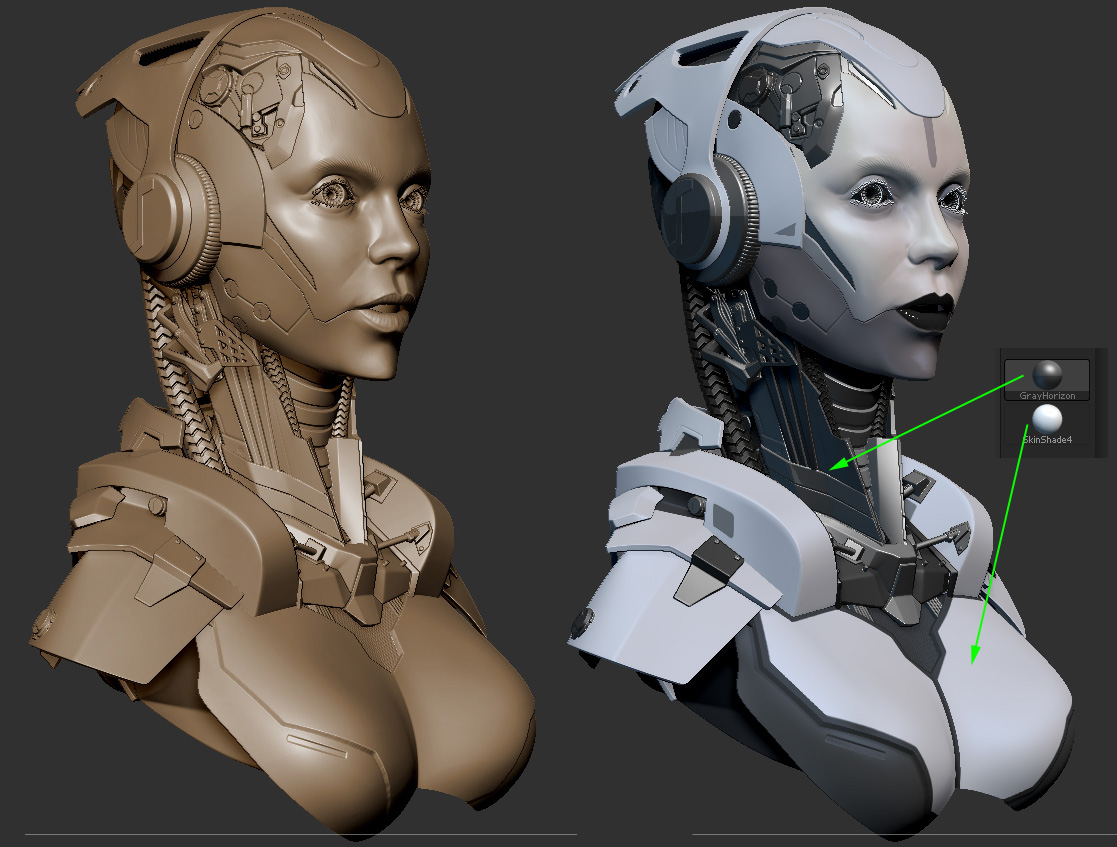
Once the geometry was finished (but before posing to preserve symmetry), I polypainted the face to match the concept. If you assign the image to a plane and drop it to the canvas in Zbrush, you can sample colors directly from it. To do this, click in the color picker, and drag over the image. I wanted some of the objects to be a white material, and the rest to be metallic. I assigned the white geo to skin shade 4 and left the rest unassigned. Unassigned subtools will use whatever material is selected. You can reset materials assignments by filling the subtool with the standard material Flat Color. I used the standard material Gray Horizon for the metal surfaces. I also added a dim blue light to the scene.
matcap_combo_02.jpg

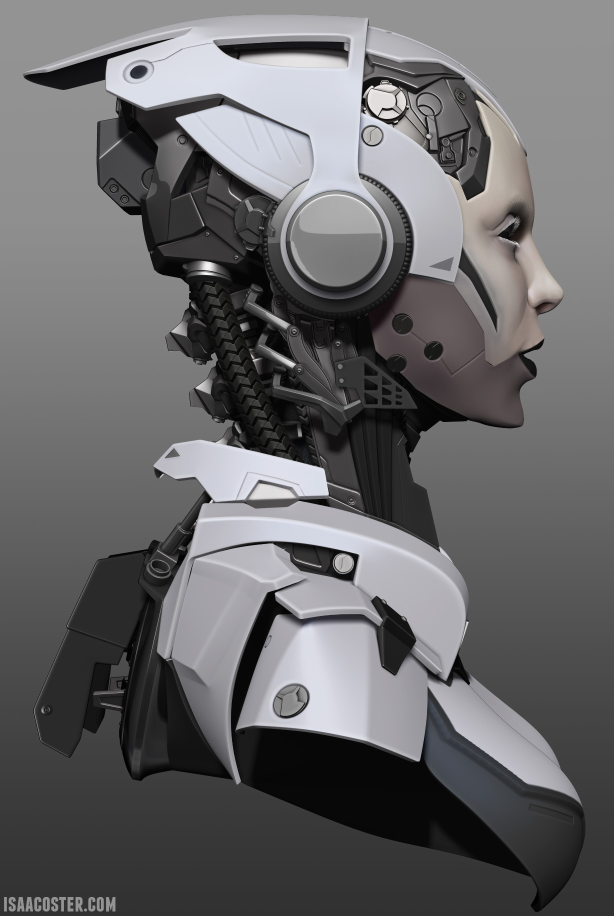
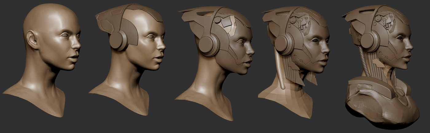
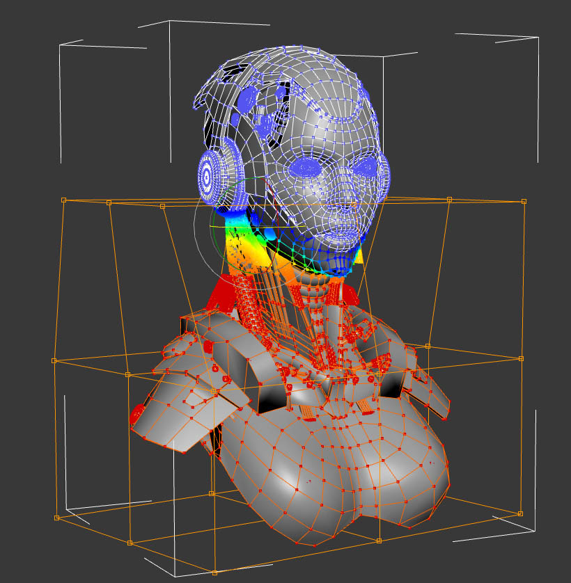
One of the benefits of creating geometry as described above is you can usually get to a low poly subdivision level without too much work. I wanted to turn the head slightly, to match the concept. Zbrush provides a very useful tool called subtool master. This reduces all subtools to their lowest subdivision level and creates a single mesh. You can then pose the single mesh, and propagate the changes to your main mesh. I needed to concentrate the deformation in the neck without twisting the face. In my experience, Zbrush is a little weird about masking multiple subtools consistently, so using GoZ, I exported the low poly tpose mesh into 3DS Max, soft-selected the relevant verts, and used a free form deformer to turn the body. I figured there was a better chance I’d want to tweak the head, so I wanted to preserve symmetry for the upper part of the model. I used GoZ to the import the modified mesh back into the tpose mesh, and Transpose Master handled the rest!
posing_01.jpg

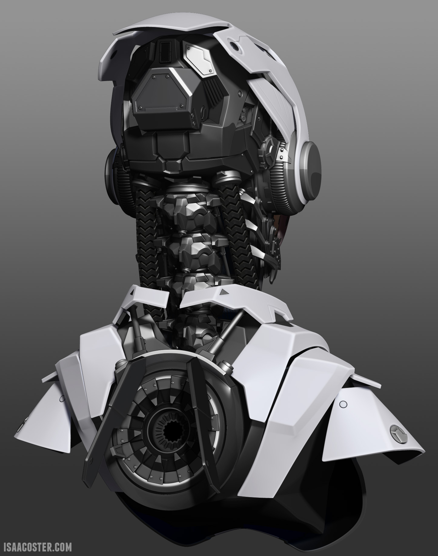
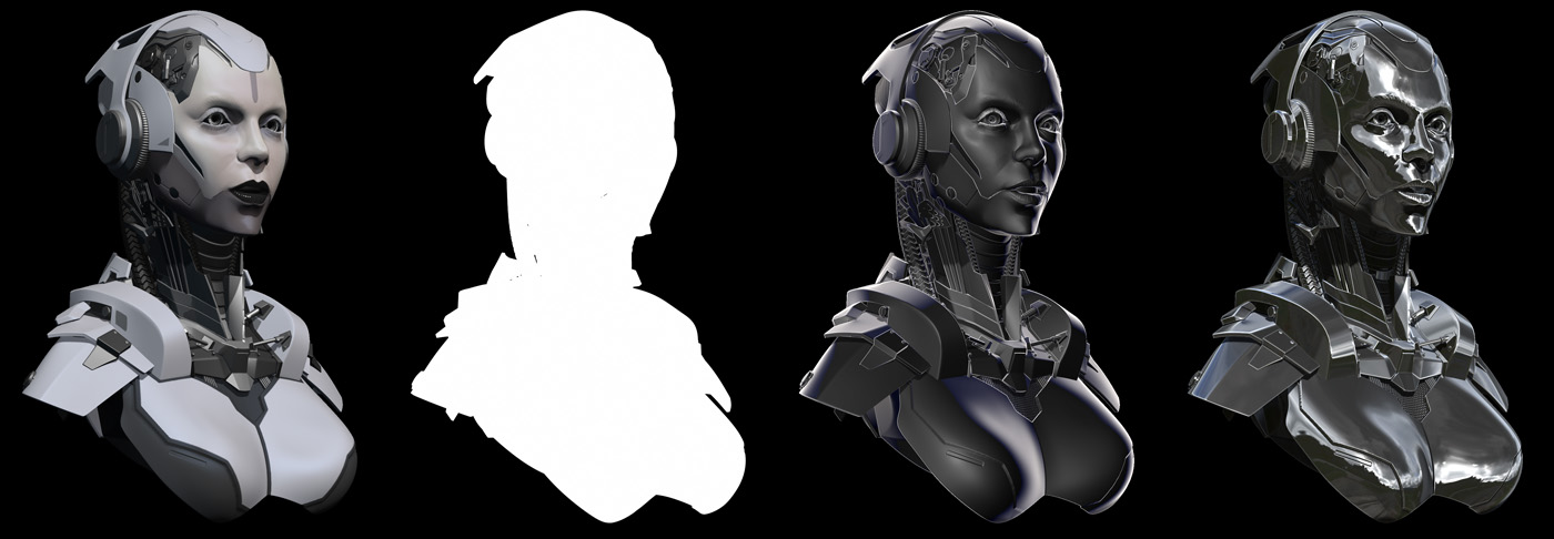
Once the materials were assigned and the pose was nailed down, I did a BPR render. I wanted to use some other matcaps in the final render, but I needed to clear the poly painting and material assignment. However, I needed to do two sets of renders, one for the front view, and one for the back view. I duplicated the file, filled all the subtools with white, and cleared the material assignment. Having two geometrically identical tools in the tool menu made it really easy to switch back and forth without worrying about consistent camera position. After some experimentation I found a set of materials that gave me what I was looking for. From left to right, this is the polypainted BPR render (skin shader 4 +Gray Horizon), the mask, a render using a graphite matcap I found somewhere, and a render using a really nice chrome I downloaded (for free) from Badking. Badking is awesome. Incidentally, the eye lashes came from an Insert Multi Mesh brush distributed by Badking as well.
renders_01.jpg

The compositing process in Photoshop isn’t as complex as the modeling, but there are still a few tricks to getting a good result. For instance, I wanted some edge lighting, which the graphite material is great for, but I didn’t want the interior of the model being edge lit - it wouldn’t make sense for lighting to get in there. I pasted the graphite render above the base render, set the layer blending mode to lighten, selected the mask layer, contracted and feathered the selection, and using this selection added a layer mask to the graphite layer. There’s a little more information about the photoshop phase of the project on my site.

Finally, One of the things that really helps with a model like this is little symbols and writing sprinkled throughout. You can make little symbols easily enough in Photoshop, but I like to look for cool fonts at dafont.com. Another thing that really sets metal off is scratch the paint off the outside edges and corners. To get this affect as easily as possible, I pasted the chrome render, added a black layer mask, and painted in where I wanted scratches. Adding a tiny amount of inner shadow makes it look like the chipped paint has some thickness. I also like to find some dirt/concrete/grunge textures online, throw them into a group, set them to almost transparent, add some kind of layer blending, and using a mask on the group paint this into cracks and tight spaces. Finally, add some lights. Paint in some glow, and try to fake how it might actually light the surrounding areas. Please feel free to ask about any part of this process, and thanks for checking out my work!

Attachments

exploded_01.jpg

noise_maker_01.jpg

matcap_combo_02.jpg

renders_01.jpg

1 Like

Thanks for sharing and taking the time to put that together.