Hi guys, i have a low poly head model from 3ds max that i want to detail in zbrush and use zmapper, whenver im done putting details on the head, when i clicked the zmapper, it says it detect multiple uv region, how do i avoid having multiple uv regions on my mesh before importing my mesh to zbrush? thanks in advance!!
When you assign UVs across multiple UV Regions / Tiles Zbrush will recognise them as such and can use them for creating multiple Displacement maps. Currently ZMapper cannot do that so you need to view one region at a time before entering ZMapper.
By pressing Tool > PolyGroups > UV Groups you can assign PolyGroups to your model in accordance with your UV Regions. Then it is a simple matter of CTRL + SHIFT clicking a PolyGroup and running ZMapper. Turn on Transform > Frame to show the PolyGroups (Shift + F).
Another solution is of course to place your UV data into one UV Region, 0,0 to 1,1 for example.
TVeyes…please tell, how is this accomplished – i have never been able to get this to work.
I’ve tried many ways, the latest is to import an object with two separate UV maps, assigned to different surfaces of the same model (in Lightwave). When I press Polygroups/UV Groups, all my polys turn the same color. I’ve been trying for over a year to get this to work, and it never does. Plus when I go to check out my UV maps with Texture/Uvcheck, there are lots of red areas – seems that Zbrush had overlaid my separate UVs in the same UV space.
I would love to be able to create separate displacement maps for different areas of a model areas in Zbrush, but no matter what I try, it doesn’t work.
Please, if there is a secret handshake for this, please initiate me!
thanks,
NJ
The problem is that although you have two maps, they still occupy the same UV space (most likely 0,0 to 1,1). In order for that grouping option to work, each map must occupy a different UV space. For example, one could occupy 0,0 to 1,1 while the next occupies 1,0 to 2.1.
Of course, that creates problems for ZMapper, but it’s really easy to deal with. Once you have your UV’s laid out that way you simply use them to define the groups. Then you Ctrl+Shift+Click on one group to hide everything else and launch ZMapper. You’ll be able to create one normal map, then return to full visibility to select another group and run ZMapper again.
Aurick, I’ve even tried arranging the two sets of UVs in expanded UV space as you say, and like it’s done in the Gnomon DVD ZBrush Production Pipeline. They are using Maya there, and I am using Lightwave, but Lightwave seems to accept it. But ZBrush still overlaps the UVs, and most importantly from what you say, does not group them with ‘UV Groups’.
I’ve also tried this:
- cut a model in two, bring each part into Zbrush separately and apply UVs
- bring the pieces into Lightwave, rename the UVs so they have different names (and thus become different maps), then stitch them together.
OR - bring the pieces into Lightwave, stitch them together, separate the UVs so they are not overlaid, but extend in UV space (all positive, as you and the DVD mentioned).
Then
4. Bring them back into ZBrush, and it still overlays them and does not work with UV Groups.
Also
- I generated separate displacements for each of the separated parts in ZBrush
- Bringing the separate parts with their ZB UVs and displacement maps back into Lightwave, the displacement maps work fine when the parts are kept separate.
BUT - When the parts are stitched together, as described above, and displacement maps are applied via separate UVs on separate surfaces (one UV applying ONLY to one surface, which had been the separate part), each displacement effects the surface it is not assigned to. It ‘sucks in’ the other surface, which seems to relate to the 50% setting for the midpoint in the grayscale displacement map. But that’s required to make the intended displacement correct. It sucks in the other surface whether the other map is applied or not.
Can anyone send me a file I can check out in Zbrush and Lightwave to see how multiple UVs/multiple displacements work between these two? I’m really going nuts here re-sculpting, redoing models and nothing ever seems to work.
Lots of work, very frustrating, as you can see.
thanks,
NJ
Hi friends,
Im heading the same problem…i need to create and export uv layout and texturing maps from zbrush to 3ds Max 8.Using GUV Tiles i have tried to export UV maps and the result was weird…can anyone help me to get out of this problem…
Cheers
Thank you for the answer. I’ve encountered the same problems in ZBrush 3.1. Everything, you said, is right. But… If you will trensfer some parts of your UVs outside of working area, HOW ARE YOU GOING TO RENDER SUCH UV TEMPLATE? (In order to paint a texture)
To paint textures you would use polypaint. This avoids the UV’s completely and lets you get a perfect match between your various maps.
After your polypainting is done, you can transfer that back to the various textures. You’d hide all the polygons belonging to other UV groups, then apply a blank texture to your model and press Tool TextureCol>Txr
There’s more info about polypainting at www.pixologic.com/docs
Thanks, but… I’ve told about “render UV template” because I have to bring normal map back to 3DS Max 9. But even hiding parts of my mesh and generating maps separately, ZMapper creates a kind of “splotchy” normal maps. I can’t understand what am I doing wrong. I have a guess, that it’s because of the mapping.
Attachments
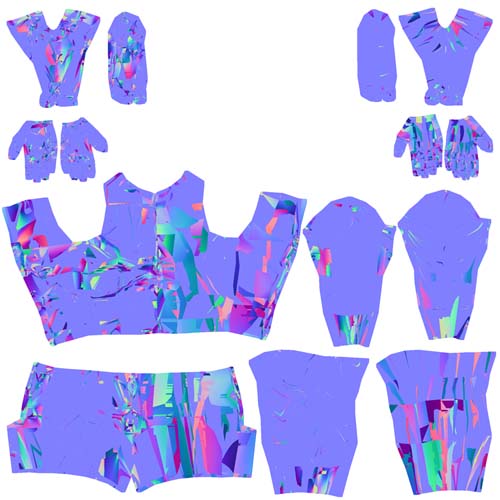
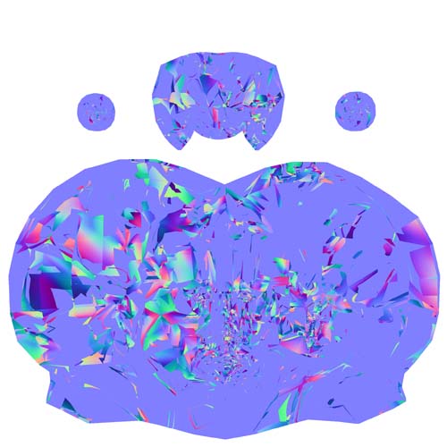
And this is my head normal map…
Attachments
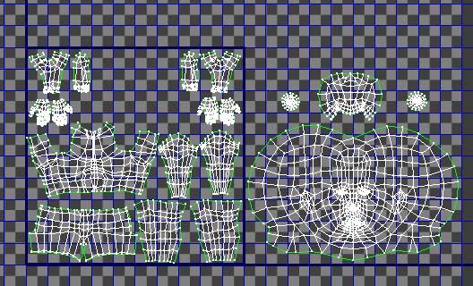
And again, if I moving some parts of my unwrap outside of the “working area” (inside blue rectangle), I see the same splotchy normal maps. But besides, in 3DS Max in order to proper texturing one can not do such things with unwrap.
Attachments
In ZBrush 3, you can’t hide the polygons you don’t want included.
Instead, press Tool>Polygroups>Uv Groups. This should regroup your model based on the UV regions. Then press Tool>SubTool>GrpSplit. Now create your normal maps for each subtool.
This really doesn’t work out. Every time I do UV Grps, -> GroupSplt, it crashes Zbrush 3.1, because I am trying to split an image with a high resolution.
I have already modeled the image in one object, so it’s got 8 levels of SubDs on it, and doesn’t play nice if you tell it to divide an object that complex.
It doesn’t seem to matter if I do this with the SubD resolution dialed all the way up or down.
I really don’t understand what is it mean - “model the image”. Maybe you talking about “tool”.
I’ve succesfully solved my problem that laid in multi-sub-object material and of cource - polygon Id of my exported mesh. ZBrush interpreted UV layout of my mesh as intersected because it doesn’t understand polygon Id.
If you trying to split your tool by UV groups, you need to separate peaces of your UV layout in your 3d modeling package (Max, Maya or whatever) to the neighbouring squares of UV space.
I cant tell you more, because I’ve never seen your model. But if ZBrush crashes, it may denote improper export settings.
Hope it will help you, good luck.
Ah- sorry about that. I’ll try to be more clear.
The problem I was having before with broken UV maps was because I was trying to follow the instructions for merely hiding the parts of the polygroup in the wrong UV coordinates. Once I learned that this feature was broken in Zbrush 3, and that dividing into subtools by polygroups was necessary, it worked.
HOWEVER- the problem I am still having is more a workflow issue. So you have to set up the separate UV maps in different quadrants of the texture grid.
This is good for Zbrush- since it doesn’t care about quadrant-- but Maya does.
Even if I export two Normal maps (one for each texture map) correctly, one UV map (in Maya) will still be displaced into the wrong quadrant. How do I go about perfectly shifting the UVs over back into the 0-1 space so that they will still line up correctly?
Yes, I understand you now. You will laugh when I’ll tell you how I’ve solved this problem 
By placing parts of my UV layout in different quadrants I’ve just made ZBrush to distinguish them as a different UV groups. Then I’ve exported my mesh in the Wavefront obj format. And after that, simply exit my scene WITHOUT SAVING.
Isn’t it as simple as effective? In max, UVs still sharing the same 0-1 space, but separated by polygon Id. But in ZBrush you’ll get absolutely correct maps, as a different UV groups.
Maybe more competent people know more “rational” workflow (if it is possible, since neither 3ds max nor Maya can’t use UVs placed out of 0-1 quadrant). If you will find another workflow, please let me know.
Good luck!
That’s what I’ve come to with my professor, as well. The problem I was having was that, by default, Maya has no way to perfectly shift a UV map from one quadrant to another (or move a set of UVs by a measured distance).
Fortunately, I was able to find a plugin, called xform, on Highend3d.com that allows for exactly that. Now that I am able to perfectly shift a UV map between quadrants- everything is going smoothely!
Thanks for the help and advice in gumming through this. Here’s hoping that later Zbrush versions offer cleaner solutions for modeling for games. =X