ZBrushCentral

Height Fields and Problems Applying Displacement Maps

We’re investigating the use of Zbrush as a terrain editing tool and height field generator for a video game. I’m running into a few problems, though.
I posted an image that I used to displace a flat plane in Zbrush, but it seems to be freaking out around the edges of the mesh, as you can see in the second image. is there something I can do to prevent the edges of the mesh from being innapropriately displaced?
I thought it might have something to do with the Quick display setting, but that wasn’t it. I also made sure the mesh’s UV’s were inside of 0 to 1.

[DisplTest01.jpg]DisplTest00.jpg

Also, is there any way in Zbrush to generate a displacement map/height field for a terrain mesh in relation to a flat plane? Like say I have a mesh of a mountain, and want to calculate a displacement map that would re-create that mountain from a flat plane. If I go to the lowest resolution mesh and flatten it, then generate the Displacement map, what I get is a flattened out Displacement map. We need to calculate the difference between the mountain and the flat plane. I can do this with Kaldera in 3ds Max, but were talking about a HUGE mesh here…

Thanks in advance,

~Mike D.

hi

no expert here but after reading a few how i did this tutorials you need to have a buffer zone on edges …if that makes sense…if you paint to the edge…its going to displace the edge.

I would create the plane…hit makepoly3d…load that tool, store it as a morph target then make it a mountain then restore level one. now you can create your displacement from the difference.

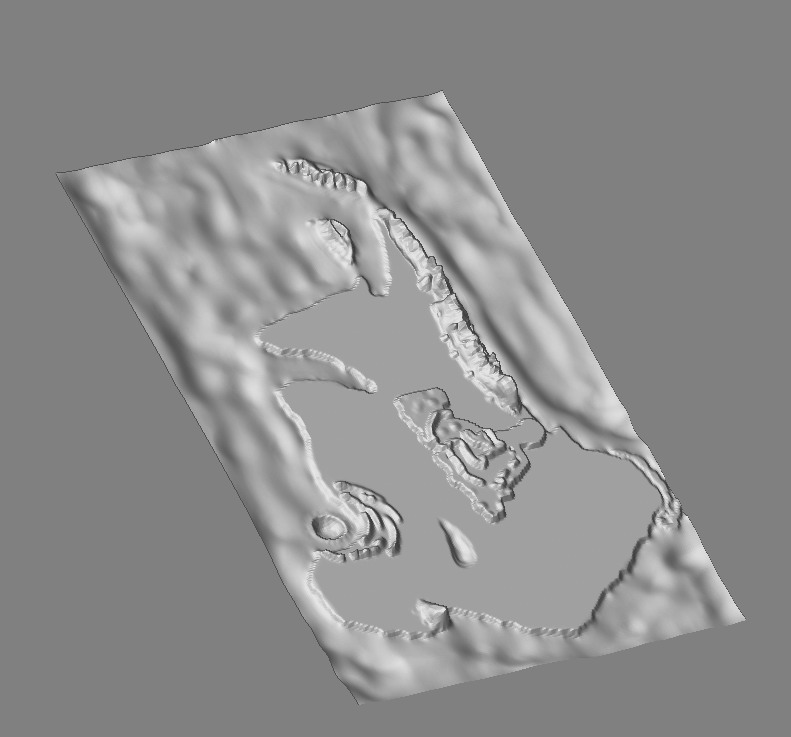
I am also thinking of using ZBrush for terrain in a project I am working on. One thing I notice is that your plane is pretty low poly. You can displace all you want, but if there are not enough polygons to displace, you are going to get this problem. Try dividing it a couple times (or more), and then try it again. I bet that this would work much better.

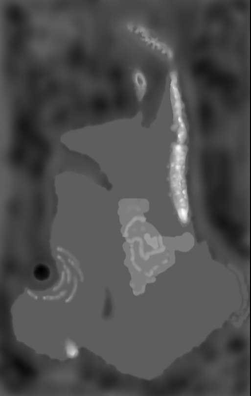
I was actually thinking of writing a zscript (although I have no idea how yet) earlier tonight for the purpose you are looking for. It would calculate the z displacement (since z would be height of a plane). The very highest displacement would be white (255,255,255) and the lowest would be black (1,1,1). This would create a height map for the entire plane. Without disclosing too much information, I am in need of a huge height map. I actually started making my map already in zbrush (we already have a nice world map, so i created it as a texture for my plane, and then made it a PolyMesh 3D, then once I added the poly tool, I subdivided it to about a million polygons. I have done little work on it so far (about an hours worth) and it is looking great. There really is no other tool like zbrush! Why would I want to go to some map editor to do things tediously, when I can already do them with ease in zbrush. Don’t even get me started on the possibilities of creating normal maps and bump maps for use on lower poly terrain to make it look great. If I can get a script that would output greyscale height maps (either as one huge height map, or have it zoom in to sections and systematically go over the entire plane in sections (and thusly creating tiles for me)) this would be the greatest thing ever.

This is what I need for my project, so I actually just started looking just now and saw your post. Kind of a coincidence that we are both looking for the same thing on the same day. I actually was in bed when I came up with the script idea, so I got up and wrote it on a post it note, and went back to bed. That was about an hour and a half ago. I was woken up by my pager for work, so I had to come to my computer to check things out, and while I am waiting to make sure everything is ok, I decided to come do a search here for height maps to see if anyone had already done anything like this.

Really cool stuff. Keep me posted. I will inform you of my progress and you can inform me of yours. If I dont find anything, I will start to research zscripts tomorrow. Good luck!

in your alpha menu, click on curve…in that sub menu you can load one of two scripts…one for a postive heightmap one for a negative height map.

not sure if that was what you were looking for…but to me…sounded like it but am tired and probably missed the mark entirely hahahaa.

anyways…after doing the makepoly3d make sure you store a morph target.

also check out the Alpha Centaury script/tutorials here and i think there is something in zhelp along the same lines…memory is fuzzy tho…need some of those other zzzzzzzzz’s.

hope that helps some.

Aminuts is correct if you want to do positives and negatives. If you want, like I do, to just go on one height map from black to white, so your lowest elevation is black and your hightest is white, don’t change the alpha at all. Leave the default alpha (which is a straight line from bottom left to top right). What you want to do is:

  1. Remove any texture that you have applied
  2. Size you plane to maximum (and still fit entirely within the document)
  3. Make sure that it is not rotated at all
  4. Go to the alpha menu and hit ‘grab doc’
  5. Now you can export your new alpha to somwhere as a psd/bmp/tif

Here is my plane with only the quick shader material:
world2.jpg
Those are beauty to my eyes. That means I am not wasting my time and can do the entire map this way!

So, if I want a script, it will only need to automatically do this procedure, and possibly zoom in and get portions (for tiles and greater detail). This is very exciting for world makers everywhere. Seriously, nothing else can do this as quickly/easily.

Attachments

ZGrab01.jpg

My latest hurdle here is when I try to zoom in and do portions for greater detail. The problem is that it goes from white to black on the zoomed portion only. Is there a way to keep the greyscale values of the entire document while I zoom in for greater detail. I do not want to create a huge document (4000x3000 or higher) to keep things how they are when I grab the alpha. I can post examples if this does not make sense. When I zoom in, the zoomed portion’s highest point is now white and its lowest is now black, regardless of what color it was when grabbing the whole. Just wondering if there is a way around this. I am content up to this point, but I would like to take this technique a bit further.

Thanks

Any depth grab from a portion of the canvas will always maximize the values. The highest space within the grab area will be white and the lowest space black. There’s no modifier to change this.

ZBrush’s maximum canvas size is 4096x4096. Since you’re working with pixols, interaction with the cavas should be fast even at that size. Is there a reason you don’t want to work with the whole map and just zoom to the parts of it that you’re working on at the moment?

Thanks for the responses.

I understand that it will displace the edge, but you can see from the image that it’s displacing it differently than the rest of the mesh. There is no line in that displacement map that should be causing the edge to displace any differently than the rest of the mesh…I just want to know if there’s a way to avoid getting that lip that forms.

Jerky, your image looks like you don’t have the same problem! How are you doing this?

The same thing still happens to me with a more subdived mesh. It just ends up being a smoother lip. It seems like Zbrush is adding values to the edges of the displacement map.

~Mike D.

To Frogspasm: I created the mesh first and took the alpha map from it, not backwards (like the way that you say you did it). I started with a plane, made it a polymesh, made a new document, imported the polymesh, then I subdivided it 5 or 6 times. I took the map that my project had made and projected it on as a texture and then started deforming. The height map was created by doing an alpha ‘grab doc.’

To aurick: That mesh has almost 5million polygons in it, so even with 1 gb of ram and pixols, it still takes a long time to move around. (My 2nd gig of ram will be here on thurs, so I will let you know how much effect that has on working with such a detailed mesh.

Is there any way to make a script that would do what I want? (ie. Zoom in and get grabs for the entire thing). The map as a whole will be split into tiles, so I would like the edges to be seamelss (even in colors, so this would make each tile have its own heights). I havent found out if adjacent tiles have to match in color along the seams or not, because if they don’t, this way of doing it will not make a difference. If, however, the seams of each tile have to have the the same color along the edges, then this will not work for what I want. That is why I am assuming 4096x4096 is not going to cut it. Say, for example, the entire map is split into 10 x 14 tiles (140 total). That would only leave me with a tile size of around 400x400 pixels. A usual height map tile in a game would ideally be at least 512x512. This is my issue. There are ways of doing it differently (like getting the output from ZBrush and then taking them and resizing them in photoshop and making sure they look good, but if I can avoid that, I would like to avoid this. The whole point of trying to do it all in ZBrush is to save time, and do the work of many just by myself.

Any ideas on other ways to do this are welcome.

Oh yeah, Frogspasm, divide your mesh a few times before you apply your displacement map. I think your problem is just that you are displacing a mesh with too few polys, hence the problems. I would suggest dividing it at least twice before you put that map onto it.

I was reading through your post wondering why you hadn’t responded to this suggestion already and I noticed that I never suggested it until now :confused: (although I meant to). So give that a try. :wink:

Here’s a possible approach for you:

  1. Resize the canvas to match the dimensions you need, but at a smaller scale.
  2. Position your object on this smaller canvas and then place a marker.
  3. Clear the canvas
  4. Resize the canvas to what you actually want
  5. Click the marker to draw the object again. It will instantly be drawn exactly how you want it without processor-intensive scaling and moving.

frogspasm-

The issue seems to be with open surfaces. That is surfaces, such as planes, that do not close in on themselves. You may notice that the problem area of the mesh is only along the poly faces at the edge of the lowest resolution of your model.

The workaround I have used is as follows:

In 3d package,
1.create poly:cube with no subdivisions. One poly face for one side.
2.layout Uvs so each face fills a different UV region. this will make it easier to hide unwanted sides later.

In Zbrush,
3. draw model and enter edit mode
4. alpha: import your alpha to be applied as displacement or just select it in your alphas
5. Texture: new texture
6. Hold Shift while pressing Geometry:Crease
7. Subdivide to the resolution needed.
8. Tool: Geometry: Display properties: Dsmooth to 1, Es to 0
9. Tool: Geometry: displacement: click Mode
10. Tool: Geometry: displacement: set intensity slider to taste.
11. Tool: Polygroup: UvGroup
12. Cntrl + Shift Click on the side you want to display. This will hide all the other sides and you can check out your displacement.

This is fairly cumbersome of a process and may not fit your needs. I hope this helps for now though till we understand the issue a bit better.

Cheers,

Ryan Kingslien

Ryan!
Thanks alot for looking into this!
I’ll try out your work around as soon as I get the chance.

~Mike D.