ZBrushCentral

Disp./bump maps,Blender,ZMapper,3DS MAX,please check it out!

Hi there,

First of all,please don't tell me to use the "Search" 'cause I did that and checked almost every thread regarding displacement maps and the only thing I learned from all this reading, is that all those disp. maps and settings within you application work pretty much individually. And another thing that I've learned is that "ZBrush to 3D MAX Pipeline" documentation doesn't work for me at all :) Okey,let's get back to the topic. So I've made a model,here is the shot of it[[img]http://img181.imageshack.us/img181/6171/front3jk.th.jpg[/img]](http://img181.imageshack.us/my.php?image=front3jk.jpg) [[img]http://img259.imageshack.us/img259/4610/back1qp.th.jpg[/img]](http://img259.imageshack.us/my.php?image=back1qp.jpg), and now I want to create a disp. map,nothing original here... My model doesn't have any UVs yet,so I'm exporting my lowest subdiv. level as a .Dfx and import it into Blender. There I make all the "seams" and hit "Unwrap".Here's the result of my unwrapping by the way[[img]http://img183.imageshack.us/img183/1534/uv0mb.th.jpg[/img]](http://img183.imageshack.us/my.php?image=uv0mb.jpg).(I've made about twenty different UV layouts and tried all of them in MAX.Results were pretty much the same).So it looks like Blender did his job and mapping looks pretty nice and clean,no overlapping,nothing. Now I export the model and import it back to ZBrush. I click "UVCheck" to see if there are any problems.Nope,no problems,just some seams here and there. So now I create a new texture 4096x4096,hit "New" and "Fix Seam" buttons.After that I create a disp. map with 4096 resolution and "Adaptive" and "SmoothUV" checked and exporting it using DExporter.Here are the settings:[[img]http://img444.imageshack.us/img444/2114/options1ak.th.jpg[/img]](http://img444.imageshack.us/my.php?image=options1ak.jpg) Everything is going OK. I load my MAX,import the model,click "M",go to "mental ray Connection" slot etc etc,well doing pretty much all the things that listed in the Pipeline documentation.But here comes the trickiest part.In "3D Displacement (3dsmax) Paremeters","Extrusion Strenght" of 2,2 doesn't work at all for me.But that's not a problem,I just play with the amount (usually it's something less than 0,7), hit render a dozen times,spend about 15 minutes to get some good results,but hey,at least I get them! So here's the problem.While the model might look quite normal,with all the veins and that stuff,there are ome "slight" problmes like those!![[img]http://img443.imageshack.us/img443/6189/bags22iq.th.jpg[/img]](http://img443.imageshack.us/my.php?image=bags22iq.jpg) [[img]http://img157.imageshack.us/img157/7774/bags0wu.th.jpg[/img]](http://img157.imageshack.us/my.php?image=bags0wu.jpg) How come? What could I possibly do wrong? I saw in a couple of threads that some people,mostly Aurick of course :) said that you should turn off MIP-mapping and any textrure filtering (antialising), but could you PLEASE tell me where the hell do I do that?! MIP-mapping? What's that? I googled around and all I could find is that it has something to do with a video card...Huh? Aaanyway,back to the displacement.As you can clearly see,there are some artifacts and the thing is,it looks like they are the result of unwrapping.This is just my guess. 'Casue when I used ZBrush GUV tiles isntead,I didn't get this kind of artifacts.All I had was a huge lack of details... Besides GUV tiles don't look very nicely in any image redactor,I mean,it's nearly impossible to work with this kind of mapping. Okey,some people said that one should try to use normal maps with disp. and bump maps to get nice results. But here is the thing. While I always thought ZBrush doesn't require a good video card,it turned out that it does when it comes to using ZMapper. Everytime I load it,I get this kind of error: [[img]http://img186.imageshack.us/img186/2261/normal4op.th.jpg[/img]](http://img186.imageshack.us/my.php?image=normal4op.jpg) and no matter what I click it just keeps repeating itself. I do think this is due to my video card.I'm on laptop and it has "Mobile Intel 945 GM Express Chipset Family" with 128MB of memory. Soo it looks like I can forget about the normal maps.

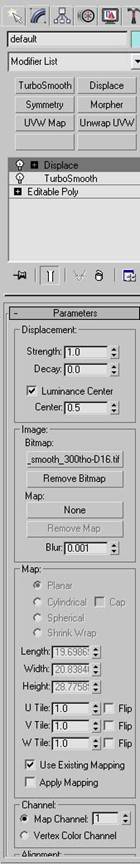
Now for the bump maps.How to generate them? No seriously,is it a whole different process or am I mistaken something? 'Casue in the “Practical Guide” in that “Making a hand” or something like that tutorial,the author generated two disp. maps,one from the highest and onther one from lvl 3 or 4,well,not the highest one, and used the first map as a bump map and the second one as disp. map. So it means,while in MAX,I would have two maps one for disp. and one for bump, right? But how come it be a bump map,while by adjusting bump amount I’m actually chaging the geomtry (well I know that I’m not doing that,but I don’t know how to say it correctly) instead of just adding/removing small details like pores and veins. So as far as I can see,it’s just a disp. map that you put in the “Bump” slot… What’s the use of this kind of a bump map then? Wouldn’t it be easier to use just one with all these details as displacement? I’m really confused right now…

So here are the questions I would like to be answered:

Is it really the unwrapping that makes those artifacts and if yes,how am I supposed to unwrap a model when even Blender’s great tools can’t do that correctly?

If those crazy "things" at the bottom of my model (there are some of those guys in the eyes too) are the result of MIP-Mapping or any texture filter,how to turn them off? Is it true that I won't be able to use ZMapper with my vide card? How to make a REAL bump map that will work as a BUMP map,not a displacement map? P.S. I do hope I don't sound like an idiot with those questions 'cause after almost two years of pure sculpitng in ZBrush I think it's about time I learn how to use my models in other apps ^_^ Software I'm using: 3D Studio MAX 9.0,Mental Ray as a renderer,Blender as an unwrapping tool.

Some more pictures:
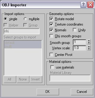
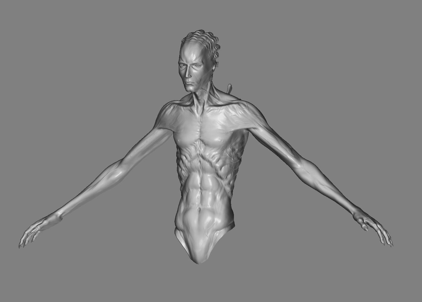
The low poly model I import into Blender

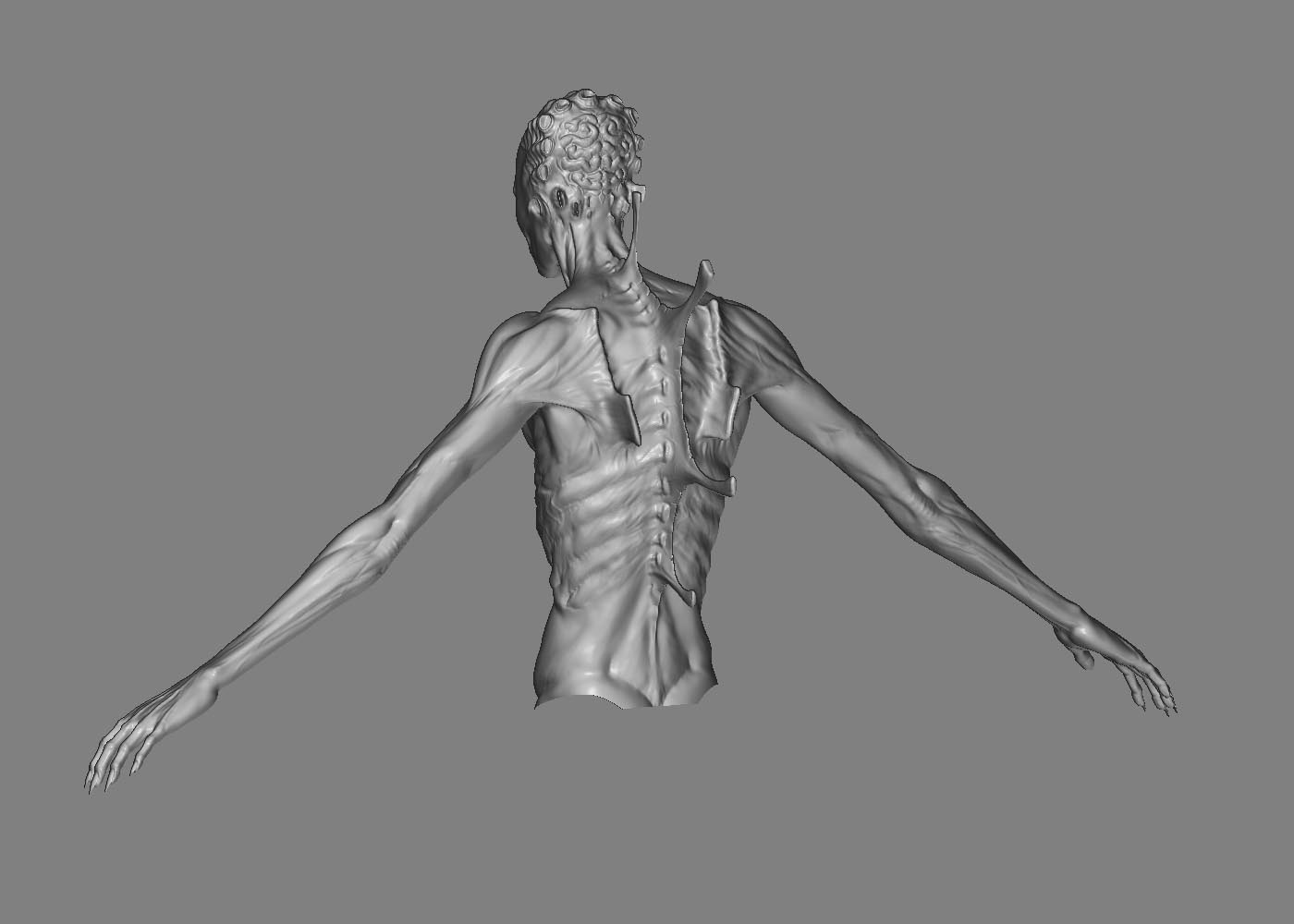
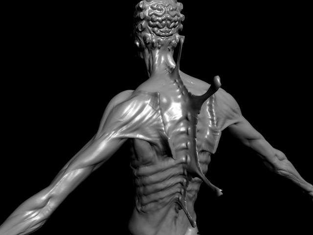
A strange bug after importng the mesh from Blender. I can easily fix it,but why the geometry is so weird looking? The other hand is fine,though…

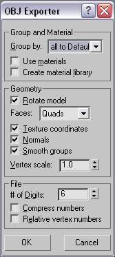
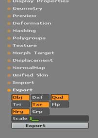
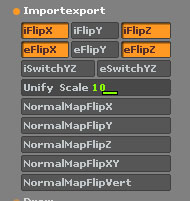
This is what I export to use it later in MAX. I also use “Cage”…

I hope someone will help me out and make some things a bit clearer for me.Sorry for the huge post by the way :slight_smile:

-Aleks

I just answered some similar questions a few days ago

[http://www.zbrushcentral.com/zbc/showthread.php?t=41290](http://www.zbrushcentral.com/zbc/showthread.php?t=41290)

As far as your artifacts, if they aren’t there when you use GUV or AUV tiles then it is most likely your unwrap is the problem.

As far as the artifacts at the bottom of your character. ZBrush has some issues with open meshes when creating displacement maps. You need to sort of create a buffer with your geometry and uvs in that area to hide the artifacts, that is the only way I have been able to get around it. So basically leave a few extra edge loops at the bottom of your character around the open area to help give more buffer to it. You could also open it in photoshop and blur out those areas manually. There are basically two ways to make a bump map that I am aware of in Zbrush. One way is this:


  • create a 4096x4096 all grey rgb (128, 128, 128) texture
  • load the bump viewer material (material that comes with zbrush found in the materials folder)
  • Paint with rgb on, with white to black values.
  • [list]
  • White bumps out
  • Grey does nothing
  • Black bumps in

  • you can paint in the view port or paint in projection master with alphas
  • when you are done painting the bump map you can view it correctly in the zbrush view port by converting it to an alpha under Texture – make alpha.
  • then make sure you have a placeholder texture on in your texture slot
  • under tool – displacement set the value to something around .05 also turn on mode
  • load any basic material (not the bump viewer material)
  • You should now be able to view your diffuse texture and your bump map at the same time.
  • [/list]I have written a few scripts that automate a lot of this process to make it easier. These can be found at the bottom of this post.

    This is the second way: If you have enough geometry and have a ton of detail in your geometry at the highest levels than there is another way to create a bump map. Normally when you create a displacement map you generate it from the lowest sub d level of your mesh (or whatever level you plan on applying the displacement map to in your other rendering software) But lets say you have 5 sub d levels, if you generate the displacement map from level 3 or 4 you will get the “difference” between the levels. So it is sort of a quick and dirty bump map.

    –E-- : Thanks a bunch for replying :slight_smile:

    I think I’ve finally understood how this bump mapping works and how to generate one. I always thought it was alot easier,though.I mean,for creating “normal” details in PM you use just Z Intensity and hit ALT where needed,while with creating bump maps it’s so much more complicated.But I think one can get used to it,just need some practice :slight_smile: And thanks a lot for those scripts,great stuff,saves you a lot of time :slight_smile:
    P.S. While “painting” a bump map,is it normal for strokes to look so crispy/not very smoothed?

    As for the second method of generating a bump map,well,this is exactly what I was trying to do. The thing is,the difference between,let’s say level 5 and the highest level (6),is too big,so when applaying the map generated from level 6 to the bump map slot in MAX,it pretty much works as a diplacement.

    About that unwrapping problem.Like I said,I’ve made A LOT of different layouts in Blender and as far as I can remember,my model always had those artifacts on the back.While posting this thread,I’ve made yet another layout and tried not to make seams on those areas where I usually have those artifacts. The result was the same plus a strange looking geometry on one of the hands.

    I aslo had troubles with the spikes on his back in MAX render,but unwrapping them idividually (I made seams around them,so they are sepearated on the layout) actually helped me.I’ll try to “collapse” the model into even smaller parts in Blender and post my results.

    As for the artifacts on open meshes,my model has legs so I don’t think there will be any issues with the lower part of the model,but what I’m worried about are his eyes. I’ll try that method you mentioned and post the results of it as well.

    I’ve made a couple more tests today and it truned out that ZBrush GUV tiles don’t solve the problem with artifacts at all.So it looks like I have to search for the source of the problem not in unwrapping,right? Where then?
    Here’s a close up of the back with all the details and a wire on it:

    And here’s what I get if I use GUV tiles:

    One important thing that it seems from your description as if you’re missing is that you’re not restoring your base mesh prior to creating the displacement map.

    When you subdivide a model, the smoothing process causes it to contract. When you return to level 1, that contraction propogates down to level 1, making it smaller than when you started. If you now create a displacement map, the map will be fore that smaller model, and the displacement values are going to be skewed relative to the actual model that you’re applying the map to.

    Here’s the correct workflow:

    1. Create your base mesh (or import it).
    2. Press Tool>Morph Target>StoreMT. This gives you a flexible and easy way to restore the base mesh later.
    3. Subdivide the model and detail to your heart’s content.
    4. Return to level 1
    5. Press Tool>Morph Target>Switch to restore the base mesh.
    6. Export the base mesh and remap it.
    7. Import the newly mapped mesh.
    8. Create your displacement map.

    If you wisth to return to a higher level again, press Tool>Morph Target>Switch first. This reverts to the multi-rest version of the model so that level 1 doesn’t cause the higher levels to change.

    Aurick: I know this workflow,but never paid too much attention too it.I mean,there is a “Cage” function that supposed to work just fine. And I always use it.
    But still. I just tried this workflow with a sphere. I pressed “Store MT” then devided the model,sculpted and moved some parts.Then went to level one and pressed “Switch”.The result was a clean sphere as expected… So how can a sphere recreate all those BIG changes in displacement map? It’s not even close to a form that I created on level 3… Okay,maybe a sphere is not a good example. Let’s say I have a humanoid model.I store the morph target,divide the mesh a couple of times making all the muslces etc etc. But now I want to make some spikes on his back! So I choose the Move tool and “extrude” some points…Or I could simply sculpt them out…I make sure that they are long enough,go to level 1 and hit “Switch”. What I get is a clean low poly mesh.I export it,map it,import back,make a disp map from level one (the very morph target) and export the mesh again as .OBJ…Now I just can’t understand one thing,how will the generated map recreate those spikes in MAX,while the difference between first and last subdiv. levels is so HUGE? I just tried that with the sphere I mentioned above,it didn’t work at all.The result were just some small bumps on it…

    Besides,what if I didn’t use that workflow? I have about 6 models that I want to render in MAX (I’m planning to create a modeling reel…) and I didn’t use this workflow on any of those. So how am I supposed to do my displacement maps the right way then? I might be missing something,though,so please correct me

    Thanks for the help anyway :slight_smile:

    lol! too funny.
    i attempting to have a mini tut made by “whomever” that would eliminate all of these questions in regards to max/zbrush displacement maps.

    all i got was read the pipeline bs.
    i am glad (and thankful) that you at least are having success in getting some answers to this. you snapshots are great along with your detailed descriptions.

    please continue to post on your progress and any other little nuggets of wisdom you get.

    This was modeled in blender? Incredible?!?! Did you zbrush for the detail or it it all modeled detail?

    As for your unwrap, make sure all of the islands fit in the square. If any islands are outside the 1 by 1 square they can cause issues when exported as an obj file. I would like to see some seam pictures so I can crit that. You seem to have way too many islands for your character and probably a ton of seams. You take care of those two issues and you should be able to take the model into any program without issues. Although you have to make sure you keep track of the orientation of the disp map and normal map.

    This is top row quality modelling though, you should post either your wip or final image in the main forum.

    DarkEdge: The thing is,I was actually hoping to create a step by step tutorial for all those MAX users who has similiar problem. I’ve been trying to make those crazy maps working for about a week and a half now and still not much luck :frowning: Hopefully,I’ll get it working and make that tutorial if needed.

    womball: The model wasn’t made in Blender :smiley: 
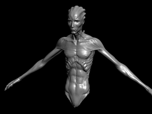
I used Mudbox for modeling and ZBrush for cleaning/smoothing/fixing some stuff and making the details. It’s still a WIP,though,got to work on the legs now…

    About the unwrap.None of the “islands” are outside the square. Blender makes sure that all the parts fit right in there. As for seams,I don’t think that hey have anything to do with the problem. I used GUV in ZBrush and had the same result in MAX ( with GUV tiling,ZBrush breaks the model into small rectangles so if you press “UV Check” you’ll see your model all covered with seams :slight_smile: ) I also tried breaking the model in about 4-5 parts in Blender,the results were even worse.Those back spikes looked all messy and that’s why I try to unwrap them individually so to say.

    As for the model itself,well,thanks I’m glad you like it :slight_smile: I’ve been using ZBrush for about two years now and never posted anything here. Don’t know why,though…

    P.S. Since I posted the images I think it would be a good thing to mention that the model is based on one of the drawnings made by Brom. I already contacted him and he was kind enough to give the permission to use his art,so there shouldn’t be any troubles with all this copyright stuff :slight_smile:

    I have gotten really good results with the blender unwrap and they should be animation fool-proof. So any pose is possible. Are you using fix seam in zbrush?

    Unknown Artist - I don’t know if you want to or not, but if you send me your .ztl with no textures or alphas. I would be more than happy to trouble shoot your problem for you.

    You can email it to [email protected] if you would like.

    womball: Yes,I use that option.

    –E--: I would gladly do that,but the model is 31mb :confused: Don’t think I’ll be able to send it via e-mail services. Any other suggestions?

    even zipped up with no textures or alphas saved in the .ztl?

    I can compress a .ztl with top sub d level around 2 million polys down to about a 16MB file when there are no textures or alphas or morph targets stored with it, when i use win rar at best settings.

    Okay,I had to delete some polys at the bottom of the model,but now it’s 10mb so hopefully everything will work.I’m about to send you the file :slight_smile:

    what about just over msn or aol IM? aol SN for me is E05B and msn is [email protected]

    Okay,let’s do it via MSN then.I’ve already added you.

    unknown artist-

    i would like to encourage you to go ahead and make that tutorial…please!

    would i be so selfish to say that even if the tutorial was just for me to go ahead and make it?
    …unfortunately for you, yes! lol!

    i have many irons in the fire but haven’t bothered with trying to figure out the max to zbrush back to max thing because there are others out there more intelligent than i that are having problems.

    once you find a method that works, would/could you be soooo gracious to send me the method???
    [email protected]

    One way to make a displacement map in zbrush:


    • Create/import a mesh that has multiple sub d levels.
    • Go to the lowest sub d level
    • Under tool – displacement set the DPRes to whatever map rez you want to create
    • Turn on adaptive
    • Turn on smooth UV
    • Hit Create DispMap
    • After it is done creating the map it will throw it into the alpha slot, but it wont select it
    • Download Displacement Exporter
    • Select your new displacement map under the alpha menu then click on DE Options, D16 button Quick Code DE-FCFK-EACADA-D16
    • You want to create a 1 channel, 16 bit, vertical flip yes, scale- auto, smooth –no, seamless –no, ch 1 range – full range ch1 res – full
    • Then export active set as a .tif to wherever you want on your computer
    • Do not edit this map in photoshop unless you know what you are doing!
    • If you want to use 32 bit float maps use code DE-LBEU-EAEAEA-R32
    • Export your lowest sub d level from zbrush to max to apply your displacement map to.
    One way to apply your displacement map in max for viewing and rendering:


    • Import your lowest sub d level from zbrush as an .obj to max
    • Convert it to an editable poly
    • You may have to select all the polys and set all their smoothing groups to just one.
    • In your editable poly options in the modifier stack under subdivision displacement set it to high in the presets
    • Assign a turbosmooth modifier to it with its render iterations set to mach the same poly count as the highest sub d level in zbrush
    • Remember zbrush counts in quads and max counts in tris, so your render polygon count will need to be double that of zbrush polygon count!!!
    • Add a displace modifer above that
    • Turn on luminance center leave it at .5
    • Load your displacement map in the image – bitmap
    • Turn on blur to .001 (if any at all) if you find you have tiny steps in your final render a 16bit displacement map should get rid of these but it doesn’t always work.
    • You will have to mess around with the strength under your displace modifier until you get it look like how it did in zbrush. Should be anywhere from .5 to 5
    • Turn on use existing mapping.
    • Now you can render it or start cranking up the iterations in turbo smooth on the view port to see it real-time in the view port.
    Some suggestions to keep in mind when creating displacement maps:


    • You want a clean UV layout. You are basically using a texture map to replicate millions of polygons so your uv layout is incredibly crucial.
    • You want use as much of the texture space as possible. Don’t have big blank spots in your texture map.
    • You want even uv distribution throughout your texture. Don’t assign a ton of texture space to the head and just a little bit to the body.
    • You want your lowest sub d level that you are applying the displacement map to, to be very similar in size and shape to the highest sub d level that you are trying to replicate. Exporting your lowest sub d level out of zbrush to max to apply the displacement map to is the absolute best way to ensure you are doing this.
    Here are some screen shots of my max import and export settings and zbrush import and export settings and a shot of my modifier stack in max for displacement.

    This modifier stack works with any renderer as far as I am aware and of course there are other ways to do this, but as far as I have seen this is the method that people have the least trouble with.

    Attachments

    clip_image001.jpg

    clip_image002.jpg

    clip_image003.jpg

    clip_image042.jpg

    34.jpg

    So I finally got Unknown Artists file and here are my results

    First two are the zbrush model.

    Second two are the max displacement renders with AUV tiles.

    I did this super quick under 1 minute so you could get better results with playing with the strength intensity in max.

    So all I did differently was assign AUV tiles to your mesh, create a new displacement map and then export out the lowest sub d level as an .obj to max and export out the displacement map as a .tif and then just went through the workflow that I stated in my above post.

    The only artifacts that I see are at the bottom of the mesh where it is open, and as I said before you can blur that out in photoshop or just add more edge loops to the open areas to keep zbrush from doing that.

    You don’t have to use AUV tiles of course, I always manually unwrap all my meshes and my displacements turn out fine. I just use AUV tiles on tests like this because it is so much quicker than re unwrapping it manually and it ensures that you are getting the best results for things like this because there is no stretching or distortions. Of course you can’t paint on it in photoshop which is why I never use it on my models. Only for quick tests.

    Attachments

    zbrushfront.jpg

    zbrushback.jpg

    max_more_strength_front.jpg

    max_more_strength_back.jpg

    Hi --E–. Im with the same problem. I tried every tutorial in this forum, include yours and nothing is working. Can I send you my model too?
    Thx in advance.