Rumi, you can unpress the SMT button in the Geometry tab before you subdivide your model and it will retain crisp edges.
Unpress SMT, divide, maybe divide again, then press SMT and divide again if needed. Should retain the crispness of the shape.
Basically it creates creases for you (from what I gather) automatically using the base geometry. When you have SMT pressed, it applies a smoothing group with or without creases or edge loops depending on how you’ve built your model. If you don’t have any edge loops or indicated any creases, then you’ll get typical smoothing group…smoothing. If you unpress SMT, you get Zbrush happily making some “auto creases” for you and you can keep your nice mechanical hard-edge shapes if you didn’t bother to create edge-loops and creases manually.
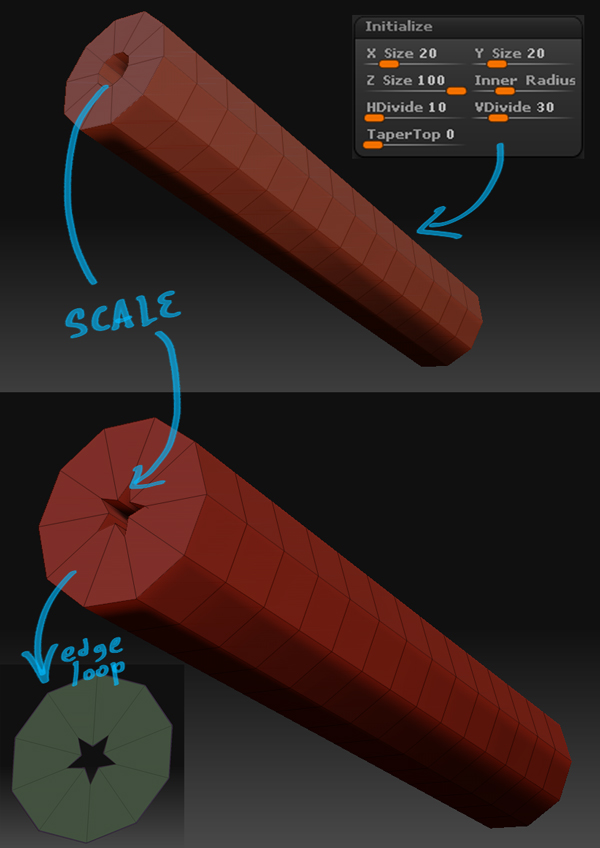
Regarding extruding your initialized primitive, just select the faces you want to extrude, hide the rest, then click “Edge Loop” in the geometry palette (to create nice edge loops), then use the deformation palette and inflate in the xyz axes. This extrudes selected faces in the typical fashion you would consider as basic extrusion in any other modelling app.
Oh and last thing, check out the video in post #197 of this thread about 3 minutes in where he talks about selecting the Outer Ring using the visibility palette for that problem you’re having with that little selection issue, that may solve it easily.
 ]
]
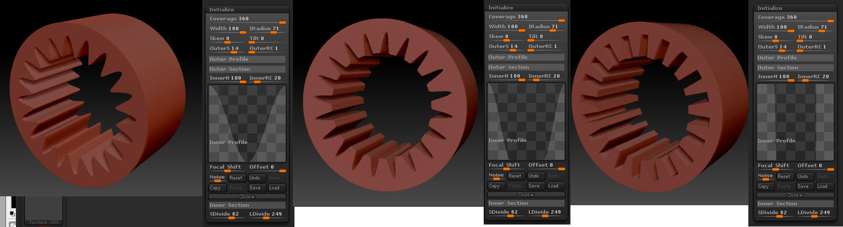


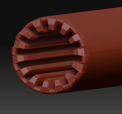
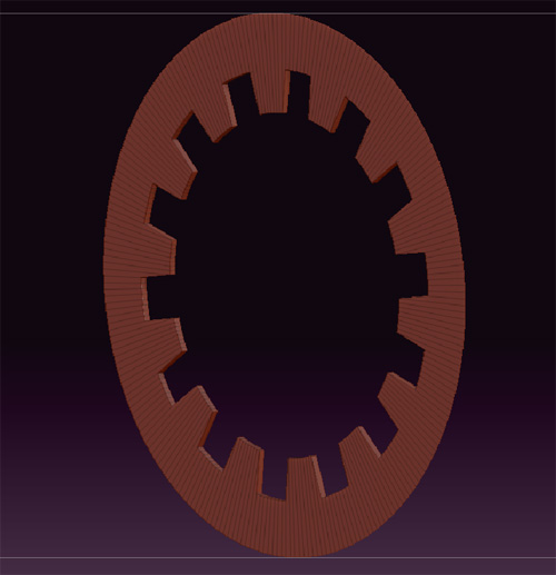
 I was like “hell, I want the indentations SQUARE not pointy face desk” but then you shown me that I could modify the shapes by editing the curves (I think I couldn’t see that panel first because I needed to click those narrow buttons with orangey patterns first to make it to pop up).
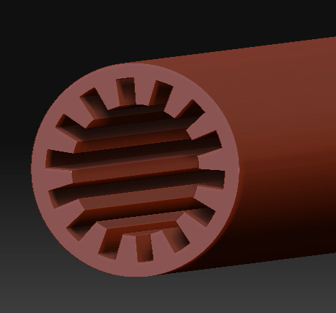 ]
]
 ]
]