I’m using the layer brush, with a morph target stored, drag dot stroke, sliding one alpha into the other. Is there any way to get a cleaner sharp intersection of the two forms ? I tried many settings but can’t seem to do it. Thanks.

I’m not certain what I’m looking at here. I’m assuming that youre working with a “ring” alpha, and have cropped out the surface they’re being drawn on for whatever reason? Correct me if I’m mistaken.
If that’s the case, I can’t say for sure why you’re getting that uneven join if everything else you say is accurate. I can only guess it has to do with some irregularity on the surface–weird angle, low poly resolution, or poor topology–or the alpha itself is somehow uneven.
With the layer brush and a morph target stored, this is what I get when moving similar ring alphas together:

Hi Scott, Thanks for trying out those alphas,
I don’t think the result I am seeing is a result of any of the factors you mention as I looked at those things.
But I can say the effect varies depending on the shape and height as you can see below. Its most pronounced on things
like the high rings. I wish I could find away to mitigate the affect.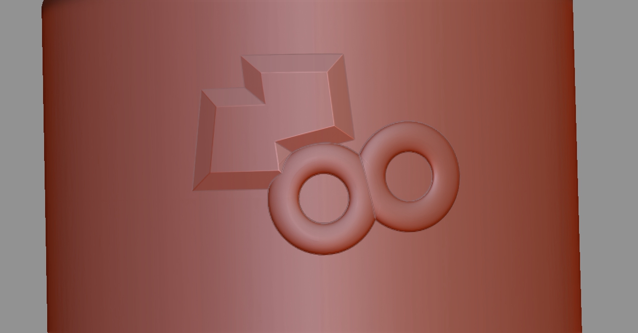
Attachments
Alright, I did it again with a much taller, custom Zbrush made ring alpha. As you can see everything is perfect as long as the surface is fairly uniform, but when I start trying to drag the alphas over corner the projection sometimes distorts, and I start getting effects similar to the one you’re showing. This is what I meant by “weird angle”. But you’re cropping out the surface these are being drawn on, so i cant get a feel for where you’re placing them:

Thanks so much Scott for that test,
The surface I was using was slightly curved but not that much really, about like this:
I have it divided quite dense, so its surprising that the curved surface could have that affect,
but that could be part of whats going on. I tried blurring the 2d alpha image of the alpha in Gimp
but that did not help. I am wondering about what other alpha creation processes , other than object
smoothness, that might have an impact on this?
Well, if your 3d tool is not perfectly parallel to the viewport plane when you capture it as an alpha, that could cause issues, but I don’t think that’s your problem.
I believe your issue is two fold. Firstly, working with a large alpha on a curved surface, it can be slightly more difficult to get the alphas to line up at the right elevation, whereas you dont have that issue on a flat surface.
But mostly, I believe you are probably working with a a high Z intensity, which is severely stretching the polygons on the side of the alpha, so they don’t deform well the next time you ask them to stretch out.
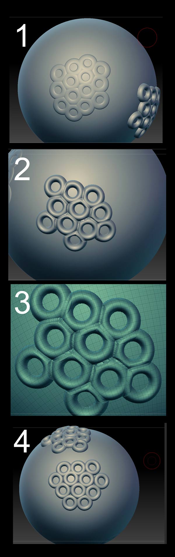
In image number 1 you can see a custom alpha working fine on a spherical surface. But when I jack the z intensity up quite a ways, you can see those odd artifacts at the join you’re experiencing in image #2. If you look at the polygons, see how stretched and distorted they are at the join (image #3)
What I think you will have to do, if you need that pronounced a shape, is to work with real geometry instead. Make an IMM brush of your ring, and draw it out on the surface by starting to draw it, then holding down Ctrl. This will constrain the size to the setting in the brush size slider to ensure the same size every time. (image 4). It may be necessary afterward to dynamesh in order to combine all the geometry, depending on what you’re doing.
Attachments
Another (old school) alternative is to work with projection master set to “deformation” and “normalize” . This will let you draw out the alphas like you do with the drag dot stroke, but because PM stamps the detail all in at once when you pick the tool back up, the polygons between the alphas dont get distorted.
PM has its own peculiarities though, and limits you to working on one area at a time.

Thanks for those other techniques Scott, I will give them a whirl.
I think you are right, this is just the way the mesh is behaving in this situation with a high Z intensity alpha.
You would think that dividing it up higher would help but it does not, seems like there is no reason for it to distort like that based on how much the mesh is being pulled, but that’s just the way it is.
Thanks again for looking at it. 
If you look closely at the mesh after you have stamped in an alpha, you’ll see that high intensity z values causes the polygons at the base and sides to become far more stretched than the polygons on the top. This is because the traditional alpha process only displaces polygons upward and downward, not outward, and the most abrupt light/dark transitions are typically at the boundary of the shape. So that’s a very few polygons that have to cover a large distance. Subdividing it more can help, but those perimeter polygons are the ones that will always bear the brunt of high z intensity distortion.
Perhaps the new 3d vector displacement alphas behave differently, as they displace in all directions not just up/down. But I havent used them yet, and don’t know how or if they respond to the maximum elevation feature associated with the layer brush and morph target.
Hi Scott, I excitedly tried a ring vector displacement alpha this morning, but the results were the same.
Thanks