ZBrushCentral

Can you generate a mirror-able normal map?

Hey everyone, I was wondering, is it possible to generate a normal map which can be mirrored?

I have a model which is just far too detailed to be brought into ZBrush as one piece, and in order to get the detail I want into the model (which is perfectly symmetrical by the way), I export just half of it from Max, import it into ZBrush, store a morph target, apply GUV or AUV tiles, apply a power of 2 texture, Divide the model, paint in bump and texture detail, export the texture, generate a normal map using ZMapper, and export the tool so I can bring it into Max 8. This all works fine. The model loads in nicely, the normal map looks great, everything’s cool.

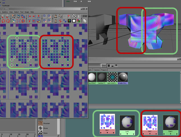
The problem obviously is when I then apply a symmetry modifier to my Max model. While the texture map is fine, the normal map now exposes a seam right down the middle between the two halfs of the model. I understand why this would happen, it seems natural enough, as the normal map will reflect what was exported (from that side), so naturally, it’s flipped on the other. Is there any cheap, quick solution for getting around this though?

Any thoughts would be greatly appreciated!

Seán

Why not use multiple UV regions and then create a normal map for each one. In ZBrush you would press Tool>Polygroups>UV Groups and then hide all but one group. Create a map for that group, then move on to the next one.

Hey aurick, thanks for replying. Can always rely on you, which is great!
I’m not sure I get the solution though. My problem is that the model is so complex that the “simple” base mesh even with a 4k texture, can’t give me the resolution I need for finer details. The same problem with deformation of the model, I get up to 1.9 million polys with the full mesh, which isn’t enough for the detail I need, and my machine can’t hack another division. If I use half the model, I can get up to 3.8 million, which my machine can just about handle. Because of this, I’m sort of tied into using just half a model and then flipping it in Max to get the other half and welding the two halfs together. Unfortunately, with only one normal map generated, there is an obvious seam where the two parts are joined together as they both use the same map.

Right hand side polys superimposed on the polys of the left hand side of the model in UV space will create an obverse~inverse flip zone seam unless you have unwelded the UV points along that seam and are rendering the model in an engine that can cope with this situation. Game engines usually can handle this.

If you are rendering in Max, you will probably have to un-overlay your left half/ right half model UVs, mirror the inverted side and either assign a new material/texture/shader (choose Max-style jargon :slight_smile: ) for the flipped half, or squash all the model`s UVs together to fit into the UV 0~1 space.

In Photoshop, copy the normal map and mirror the copy, moving it to fit over the appropriate UVs. The last thing to do is to inverse both the red channel and the green channel, so that each channel`s blacks become whites and the whites become blacks. Doing this will fix the valley-to-mountain inversion that the mirroring caused.

Cheers,

R

That’s cool Rory, thanks for that! As it turns out I’ve come across a small problem, whereas before I thought the model would be perfectly symmetrical, it turns out that parts of it aren’t, so I had to find another solution instead.

So I’ve gone with making the texture an alpha, using the Displacement Intensity to make that alpha apply a quick bump for me. Then I make that alpha my texture, so I can edit it in PM using greyscale values to get additional bump, finally reapplying my original texture, but keeping that alpha to use as my Displacement Intensity alpha, and generating a normal map using Zmapper. Seems to work fine. Possibly the same thing as using the bumpviewermaterial, but it seems to get slightly better results for some reason. But that’s possibly just my imagination getting the better of me. Wouldn’t be the first time.

Still, your solution seems quite ingenuous and makes sense to me - except for inverting both red and green channels. I get why one of them would have to be inverted, for the horizontal flip that’s just happened, but as there was no vertical flipping, I don’t get why the other colour too. Not to worry, possibly too hard for my feeble little mind to wrap itself around anyway. Sometimes ignorance is bliss and just knowing the procedure is good too. Thanks for the help! It will definitely come in handy some time in the future, that much I know. Normal maps are becoming far too important to me to not use that information at some stage. Cheers man!

Seán

Youre right: its just the red channel only, isn`t it? I was away from my regular computer yesterday and was explaining the procedure from memory.

Glad you found a solution anyway.

Cheers,

R

I’ve made several posts here explaining how to split your model up into multiple parts. You can then divide each part to the max number of polygons that your computer can handle, giving a greater polygon count across the whole.

This is especially useful if your model has been UV’d into multiple regions. That way, you can have multiple maps which will give a greater numer of texture pixels – lots more detail!

Thanks again Aurick. I gave it a go, but without as much success as I’d like. I do exactly what you say (I hope!):

  • Import single OBJ file
  • Apply a 4k texture
  • Apply AUV tiles
  • Hide half the polys
  • Clone the tool
  • Delete the hidden polys
  • Crease
  • Store Morph Target
  • Go out of Edit mode, Clear the canvas and drop the other half onto it.
  • Now because this cloned model doesn’t have a texture applied to it, I invert the selection and apply a new 4k texture to it. If I don’t do this, for some reason the generated normal map is not 4k, but 2k, which then doesn’t fit my other half.
  • Delete hidden polys, Crease, and Store the Morph target again.
  • Divide the model, detail it, go back to Subdiv 1, Switch the morphtarget and use Zmapper with the correct settings for Max 8 to generate the normal map. When map is generated, export the model. Everything is cool, a 4k normal map is generated. Bring it into Max 8, renders fine.
  • Go out of Edit mode, clear the canvas and drop the other tool onto it.
  • Divide and detail as required. Go back to subdiv level 1, Switch the morphtarget and use ZMapper to generate the normal map. Again, everything looks good with the model rendered on it’s own.
  • Put the two models together in Max, apply the two different normal maps to each half of the model. Render and get a seam, which is expected, as the verts haven’t been welded yet. Weld them, and you STILL get the seam. The normal maps don’t appear to line up at the edges, creating this seam. Just to check, I put a standard empty material on the model, rendered again, no seam. Add the normal maps, seam is back. Use just one normal map on one side, and you get the seam (obviously).
  • So I start to think it’s me. So I open up Photoshop, bring in the 2 generated normal maps and copy one into the other, expecting them to line up. While they are close to matching, they don’t. Some of the tiles are just bigger, some longer, etc. They just appear to be different shapes so they don’t line up quite right.

Any ideas? If you follow these steps, is it reproducable for you? (or anyone else) The theory behind it makes sense to me, I’m just not sure where I’m going wrong. Again, I really appreciate the help on this aurick, it means a lot to me to get this done. Anyone else who might have tried this technique aswell may have spotted where I’m going wrong. If I could get this working, it would open up a whole new world of ZBrush to me!

Sean
P.s Thanks Rory for getting back to me. As you can see in my other solution, I’m still having problems there too. Learning alot though, so that’s positive.

  1. Lay your UV’s out in another program, using multiple regions. Each region is a single UV space, such as 0,0 to 1,1 (the default UV space), 1,0 to 2,1, 0,0 to -1,-1 etc.

  2. Import the model

  3. Press Tool>Polygroups>Uv Groups

  4. Create a clone of the model for each group

  5. Ctrl+Shift+Click on a group to hide everything else

  6. Press Tool>Geometry>Delete Hidden to delete everything else

  7. Press Tool>Geometry>Crease to prevent edge contraction when subdividing.

  8. Divide, sculpt, and create your normal maps

When you take those maps back into your other software, you’ll apply each one to its appropriate UV region.

As far as I can gather, all that the laying out of UVs in Max will do for me is help me to create polygroups, right? So it’s easier for me to select half my model. I wouldn’t have considered that much of the problem in the first place anyway, as I’m selecting exactly half of the model without any trouble. Have I got that right?

Anyway, I’m obviously still doing something wrong. I followed your steps, adding in the necessary part for the maps too (step 4b), and maybe that’s where I’m going wrong…

  1. Lay your UV’s out in another program, using multiple regions. Each region is a single UV space, such as 0,0 to 1,1 (the default UV space), 1,0 to 2,1, 0,0 to -1,-1 etc.

  2. Import the model

  3. Press Tool>Polygroups>Uv Groups

  4. Create a clone of the model for each group


4b) Create a 4k texture and hit Auvtiles for each of these clones


  1. Ctrl+Shift+Click on a group to hide everything else

  2. Press Tool>Geometry>Delete Hidden to delete everything else

  3. Press Tool>Geometry>Crease to prevent edge contraction when subdividing.

  4. Divide, sculpt, and create your normal maps

I still get the problem. Any ideas? Am I creating the textures or the AUV tiles at the wrong time or something? Has anyone else tried this technique and got it to work? It would be so cool if it did…

Sean, 4bs the problem! Youve already made your UV maps in Max, so why are you making them again in Z-Brush?:confused:

R

Ah no Rory, all I did in Max is take half the mesh and apply a planar map to it, just so I could move it into it’s own UV space, so when I hit Make Polygroups in ZBrush, it would automatically make the two groups (one for each half). The model itself is far too complex to unwrap manually, I’m forced into using AUV tiles, (which I like anyway). I presume this is the reason aurick said to do this when making the polygroups, just to make sure they are done right.

The thing is, when you apply a texture to a model, complete with AUVtiles, and then clone that model, the cloned model doesn’t get a texture, so you have to apply a new one to it. This is also the reason that I create the two 4k textures and AUV tiles AFTER the cloning and BEFORE deleting the other half of each model, to be sure that they both have the same AUVtiles for the same size texture. It doesn’t seem to work though. Which is really strange. These are both effectively the exact same model (clones), when I apply the same sized texture to each, and I presume when I hit AUVtiles it always calculates them to be the same (after all, it’s the same model with the same sized texture it’s applying them to), so I don’t get why they don’t fit each other perfectly afterwards. Any ideas on that even?

Ok, don’t want to harp on about this, but I’ve simplified it down to a very simple test. If anyone else could try this out and see if they get the same results, I’d be very interested. It looks like a long process, but I promise it would only take you 4 or 5 minutes to try it.

  • in Max, make a simple shape like a torus.
  • apply a planar uvw map to half the torus and using a UVWUnwrap modifier, move it into it’s own UV space.
  • export the model using usual settings
  • in ZBrush, import the model, go to Edit mode
  • Tool, Polygroups, UV Groups, turn on Frame to see result - model should have two groups
  • apply a 4k texture to the model and AUVtiles
  • Clone the model
  • Ctrl+Shift click one half (say the right) to hide the other half
  • Tool, Geometry, Delete Hidden, then Crease, and then Store a morph target
  • divide and add some detail somewhere
  • go back to base level, Switch morph targets and using Zmapper with max settings, create normal map and export tool
  • go out of Edit mode, Ctrl + N to clear canvas
  • select the other clone and draw on canvas. Go into Edit mode.
  • apply a 4k texture to this clone and hit AUVtiles
  • Ctrl+shift click on the left half to hide the right half
  • Tool, Geometry, Delete Hidden, then Crease, and then Store a morph target
  • divide and add some detail somewhere
  • go back to base level, Switch morph targets and using Zmapper with max settings, create normal map and export tool
    In max, import the two models and use the exported normal maps. Attach the two models together, welding the verts to get rid of any seams (in the viewport). Render with the normal maps, and you still get a seam!

At least, I do.

Anyone else?

Did I do something wrong somewhere? You’ll notice I always applied the 4k texture and AUV tiles to the both versions of the model BEFORE I delete any polygroups to ensure that they will be the same. And yet, when I bring both of them into Photoshop, they don’t line up!

Sean

The reason for creating the UV’s in multiple regions in Max is NOT for selection purposes. It’s so that you can apply different maps to those regions. You then use ZMapper to create two separate maps, and those maps will look right for each region when applied to that region.

What you are doing with the steps that you outlined is to remap the model with Tiles. The problem is that remapping in ZBrush applies to your ENTIRE model, regardless of whether it’s partly hidden or not. YOU CANNOT USE ZBRUSH TO CREATE MULTIPLE UV REGIONS. This is why you are having problems. By adding 4b you have eliminated the multiple regions and remapped your entire model to a single Tiles-type map. In short, you’ve put yourself right back where you were before you ever came onto ZBC for help.

In Max, apply your FINAL UV mapping to the model with each part in its own UV region. Do NOT remap the model after importing it into ZBrush. The regions are not selection placeholders; they are the final UV mapping that your model will use.

Hi again Aurick, and again, thanks for getting back to me. I seem to have misunderstood things apparently. Sorry about that. Unfortunately, as I said to Rory, I can’t unwrap this in Max, it’s just far too complex a model to do that, that’s why I wanted to use AUVtiles instead.

So does this mean that I can’t create multiple normal maps on one model that will line up later if I am using AUVtiles?

P.s Sorry, just reread your post, obviously that’s what you meant when you wrote in capital letters that I cannot use Zbrush to create multiple UV regions. There’s no work around for that then, other than to do the unwrapping somewhere else?

Try this:-

Bring the .obj model into Z-Brush and GUV or AUV tile map it.

Export that model.

In Max, select one half of the model and delete it. Can you see where I`m going with this?

Copy-Mirror the remaining half model.

Flip this new half`s UVs and drag them to a new UV unit space.

Re-export the whole model.

Import the model into Z-Brush.

  1. Press Tool>Polygroups>Uv Groups.

Save the model as a Z-Tool. Save it under a new name for each part of the model you intend to hack it up into.

Continue with Aurick`s method from point 5 onwards:-

  1. Ctrl+Shift+Click on a group to hide everything else

  2. Press Tool>Geometry>Delete Hidden to delete everything else

  3. Press Tool>Geometry>Crease to prevent edge contraction when subdividing.

Repeat steps 5, 6, 7 for each saved part tool.

  1. Divide, sculpt, and create your normal maps

How does this sound to you? Seems right to me, but I haven`t tested it.

Cheers,

Rory

I’ll give it a go Rory, cheers! Was thinking along the same lines myself, but it’s nice to see it written out in steps. Cheers man.

Hmm… the steps seemed right to me too, but the results were quite amazing actually. NEITHER half worked properly in ZMapper. The results were just terrible, I didn’t even get one normal map to work properly. It just looks like every face normal is wrong. I followed the steps, making sure to flip the UVs for half the model horizontally and putting them in their own UV space. Not sure why it didn’t work, it just didn’t. Ah well. Back to the drawing board.

I have just tried the procedure. There is nothing wrong with it per se, though, as I`ve written in other threads, I like to have a two-poly deep rim of buffer polys at the open edges of the chopped off body parts.

This screenshot shows the model that was GUV tile mapped in ZB and re-imported into Maya, with the normal maps generated for each side assigned to separate materials and their respective polygons.

The lack of success you experienced may be Max pipeline specific. I can`t help there, only having Maya and LightWave to hand.

Cheers,

R

Attachments

TestModelScreenshot01.jpg

So it IS doable then… must investigate further. Haven’t come across your buffer poly threads yet, must do a search on that too. Of course, as I write all this, schedules are forcing me to just push ahead regardless, and I’m thinking this is something I’ll have to come back to rather than get to the bottom of right now. Anooying, but what can you do. Thanks for all the help anyway! Glad to hear it’s possible at least, just a matter of figuring out where I’m going wrong.

Sean

P.s Just looking at your screenshot there, are you sure there’s no seam at rendertime? I can almost spot one there…