ZBrushCentral

Boolean Workflow: Slicing Model w/ Interlocking Registration Bumps?

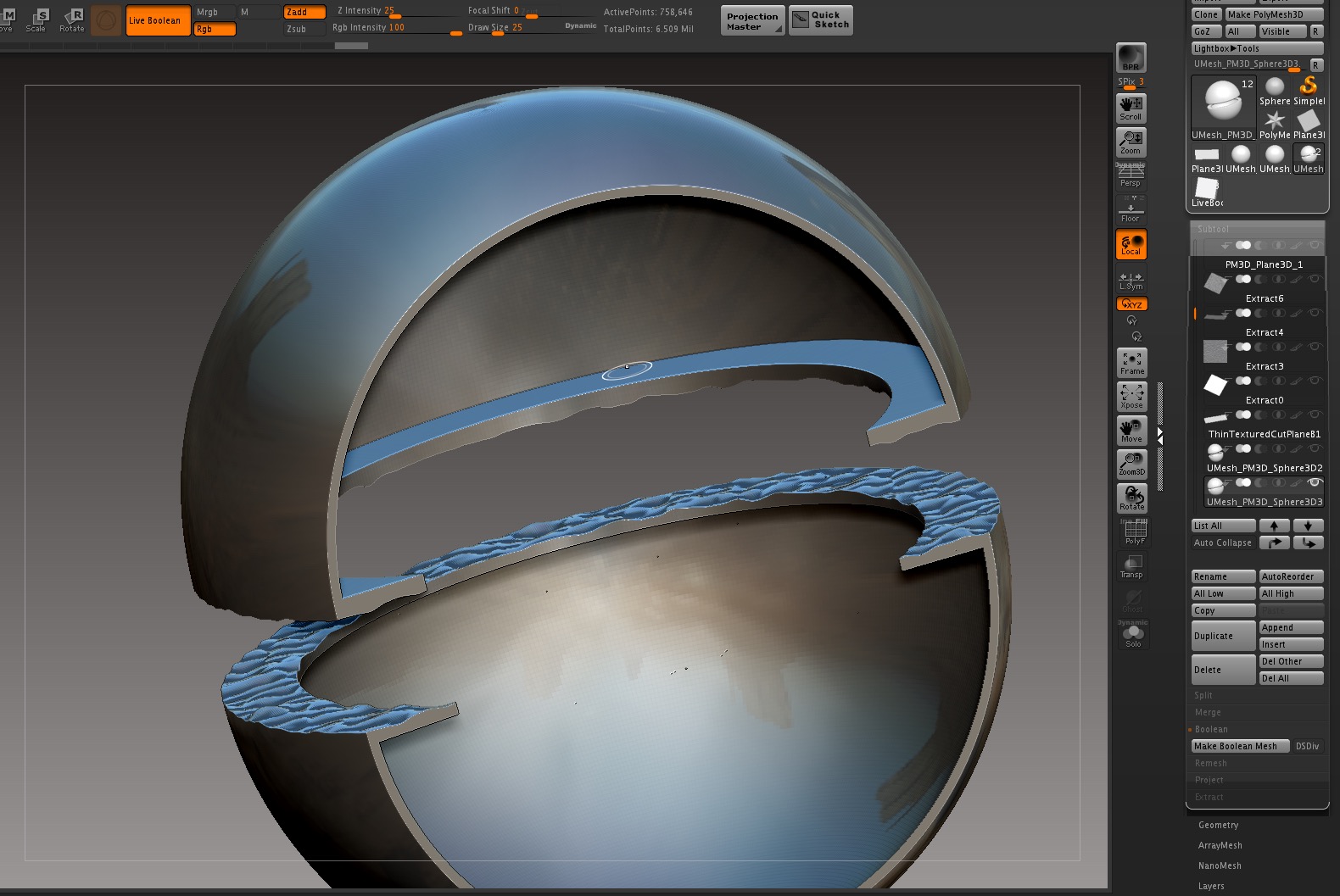
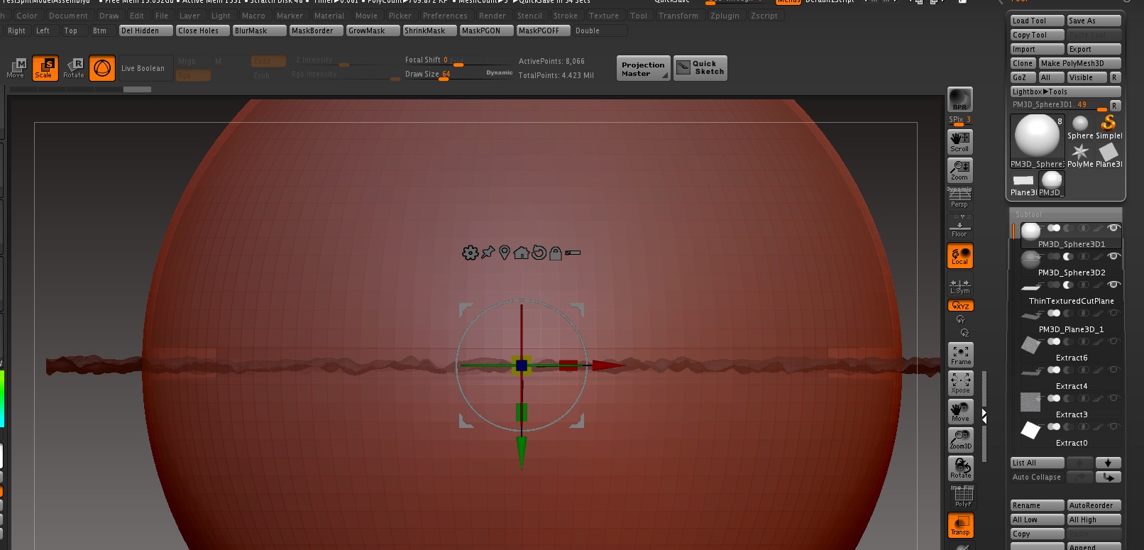
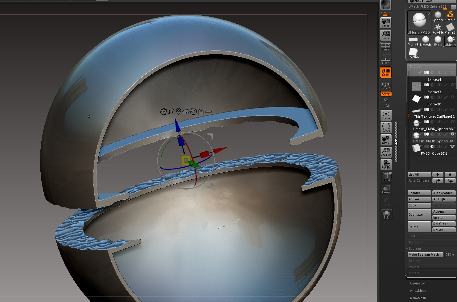
Any (boolean?) workflow suggestions for- slicing through a mesh, creating 2 parts

  • each side of the resulting mesh having mating bumps or keys to help register the two halves after 3d printing.

I’d like to more easily chop up my models for 3d printing, and at the same time, create bumps or keys on both halves to assist in fitting the parts back together.

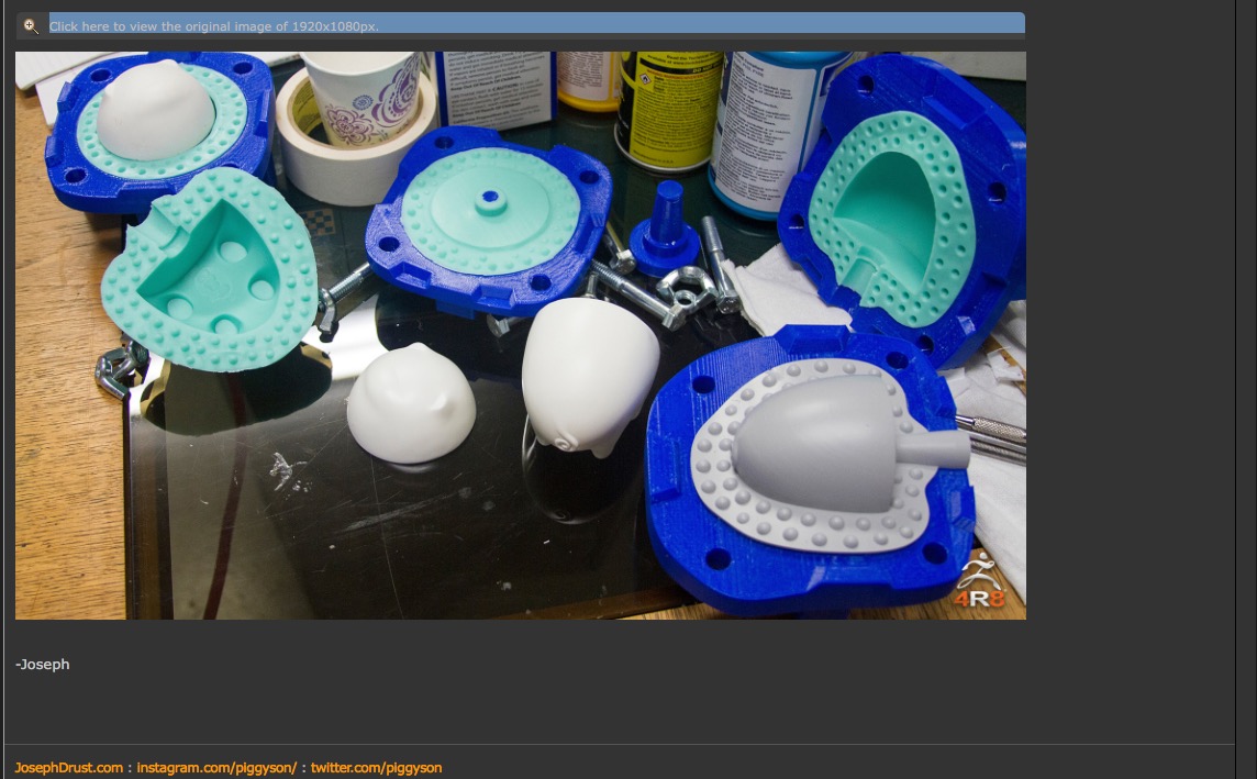
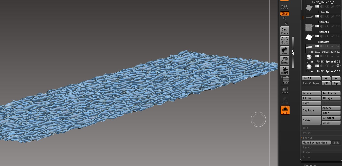
The image below is from Joseph Drust’s 4r8 demo where he is using hemispheres and irregular cuts as the keying features.

I assume it’s a pretty common practice used to break up models for 3d print.
I have a feeling that I am making this too difficult.

thanks!

Screen Shot 2017-09-08 at 5.56.49 PM.jpgScreen Shot 2017-09-08 at 6.22.16 PM.jpgScreen Shot 2017-09-08 at 2.57.51 PM.jpgScreen Shot 2017-09-08 at 6.18.34 PM.jpgScreen Shot 2017-09-08 at 6.23.35 PM.jpg

Attachments

Screen Shot 2017-09-08 at 5.56.49 PM.jpg

Screen Shot 2017-09-08 at 2.57.51 PM.jpg

Screen Shot 2017-09-08 at 6.18.34 PM.jpg

Screen Shot 2017-09-08 at 6.22.16 PM.jpg

Screen Shot 2017-09-08 at 6.23.35 PM.jpg

You just need to create a thin box and use the standard brush to pull out the little bumps where you want them.
Sounds like you are for sure making this far more difficult than you should.

Thanks @beta_chanel, that would be easy.
When i tried that before, I got some holes in the resulting mesh at the cut interface. I suspected that it had something to do with my thin box developing problems (coplanar polys, overlapping vertices?) as the tool pushed and pulled on both sides of the mesh. Or maybe my box was too thin? I’ll try that again.

Any suggestion for a brush or brush settings to use on thin stuff? I think i just used the move brush with default settings (alt-click-drag for normal).

Thanks!

Personally I would actually work on a plane first then add thickness to that.

OK.
How would you add thickness to a single sided plane? That’s what I was trying to do with Extract.

Zmodeler QMesh?

QMesh seems to work, but having trouble controlling the thickness and making it as thin as mathematically necessary.
You’ve already helped tons, but if you have any suggestions on controlling/defining the ultra-thin thickness, I would appreciate it.
Qmesh/PolygroupAll/NoAlignment seems to allow a very thin mesh, but it’s by eye and not repeatable as far as I can tell. Step Size did not do what I thought it might. And I didn’t find much on the web on the topic.

thanks again!

Dupe your mesh (for reference of original position)
Store a morph target
offset your mesh either by eye, or use the deformations ,which can be repeated and standardized, to the distance you want the mesh to be thick
creatediff mesh

That works great. Thanks @beta_channel!!

PS I did the deformations in 2 steps. Otherwise I ended up with some coplanar polys:
To summarize:

A. Append a single sided cutting plane subtool
B. Sculpt interlocking features onto the plane (with no undercuts / negative draft angles)
C. Duplicate sculpted plane mesh for visual reference. Turn transparency on.
D. Set morph target
E. Deform the single sided mesh:1. Deformation/Offset in one axis to create the parting line cut/gap and to eliminate coplanar polys parallel to the parting line.
2. Then Deformation/Inflate (in the remaining 2 axes) to create some clearance and eliminate coplanar poles.
F. MorphTarget/CreateDiffMesh
G. Append the resulting MorphDiff Mesh
H. Use the new morph diff mesh as boolean subtract cutting tool

Then I confirm that it worked by polygrouping, viewing the 2 halves of the cut mesh with Polygroups/AutoGroups.

A candidate for a macro perhaps :slight_smile:

Thanks again!
Screen Shot 2017-09-10 at 9.28.40 PM.jpg