I am having a terrible time generating a displacement map
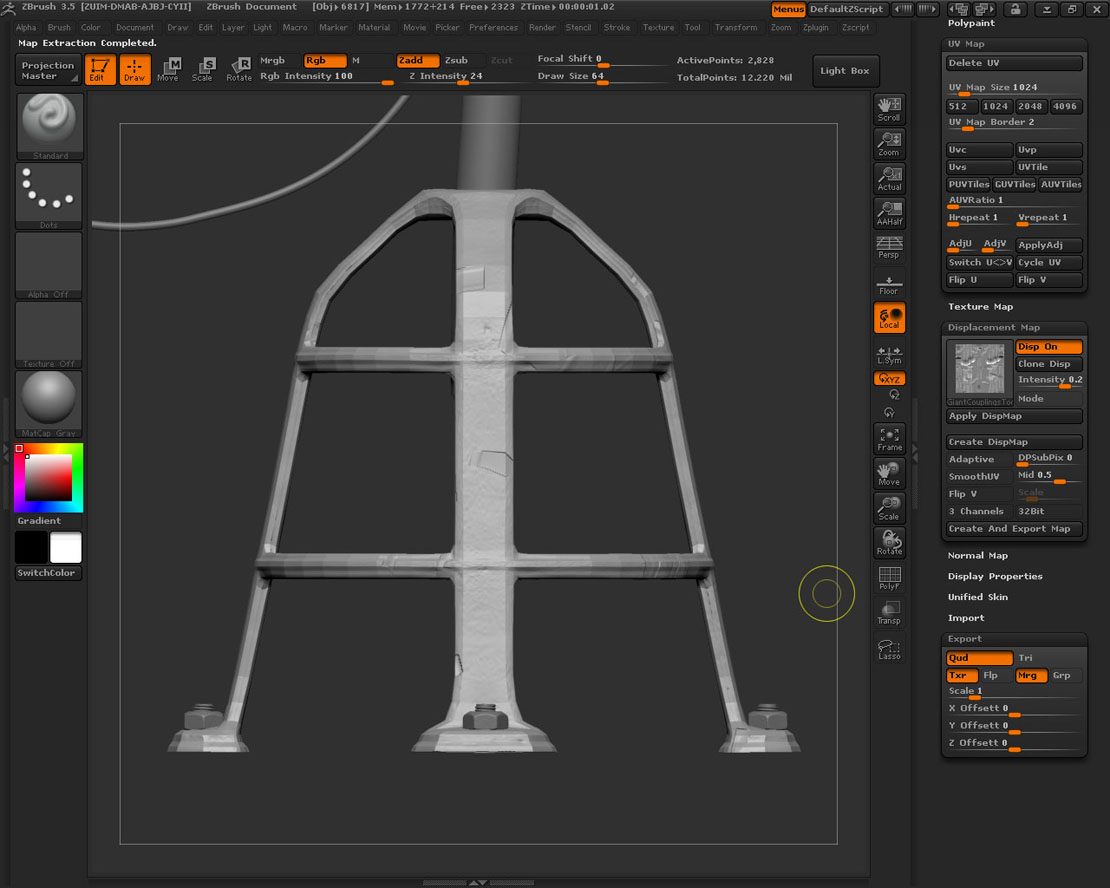
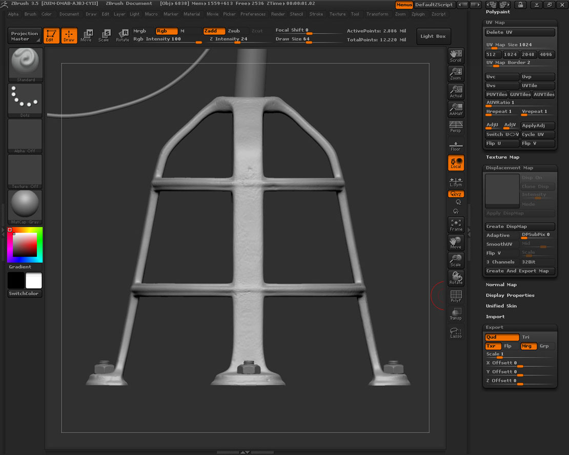
I have attached screen shots to show what’s happening when I try. There’s one shot with the ZTool in it’s highest subdiv level so you can see how it should look.
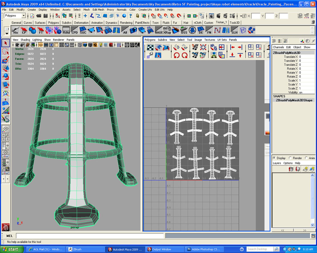
The next shot is of the tool at it’s lowest subdiv level with a displacement map generated – see that it doesn’t fit properly.
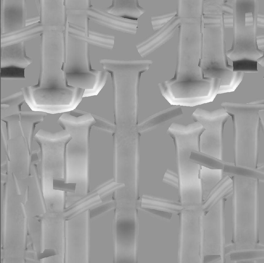
There’s a shot of the map from ZBrush. It looks like the UVs have been wirdly rearranged and super imposed, which would explain why the map looks the way it does when projected on the tool. Again, I’m sure there’s a ZBR solution but I don’t know what.
I have also attached a screen shot of the tool in Maya so you can see the UV layout.
Here’s one more bit of info: When I export the tool as an obj from Zbrush in to Maya and open the UV editor I find all of the UV edges have been cut. The UV map is the same as in my enclosed screen shot, but all of the UV edges are separate. The first time this happened I laboriously sewed all of the edges without changing the layout, re-imported in to ZBrush and…no change.
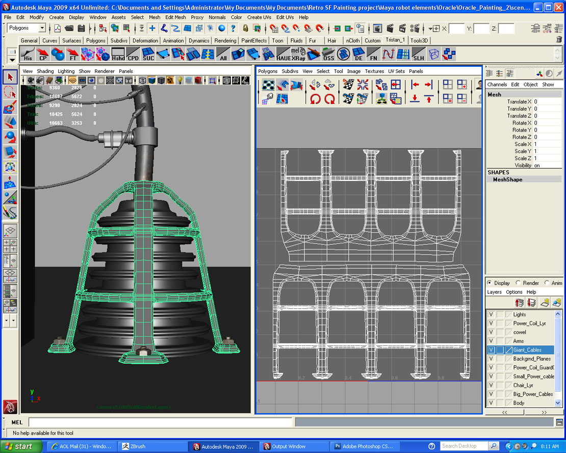
I have also attached a shot of the mesh in Maya with a better UV layout. However, apparently the shape of the mesh had changed slightly from the mesh I used to fix these UVs. So, if I try to import this UV in to the tool in ZBrush the tool gets even more distorted. I’m sure there’s a work around for this (the point order is the same) but I don’t know ZBR enough to know how to do it.
Very frustrating.
Any one with any ideas?
Attachments