ZBrushCentral

Z Brush 4r7 tips ,,(Zmodeler)(nan mesh)(array mesh)(zremesher2.0)

I like this, thanks Spyndel / Scott!.

You can create arches with ZModeler as follows:

  • first create your two colomns, then delete the two top polys (ZModeler, Polygon, delete)

  • Tools>Display>Double so you see both sides of the polys

  • Edge mode, and Bridge, choose bridge two holes and choose arch

  • select the inmost edge of the first hole, then the inmost edge of the second hole.

  • this creates a flat connection, but dragging left and right, and up and down changes angle and number of polys

@DesignitLive

Actually, you can’t really do that. Zbrush doesn’t support polys with more than 4 points. If you examine you mesh closely, you’ll find that what you have there is one giant quad, and some stretched, almost invisible polys in between the edges connecting to the corners, which are going to be problematic in time.

For instance, if you enter dynamic subdivision mode, you’ll see you have some “tears” in your mesh there.

Eric Keller added a video tutorial on the creation of tentacles to his Vimeo channel:

https://vimeo.com/118219444

@Spyndel Yeah, ok, i’ve seen. Maybe you have right hmm. But if you use this method and you go later in DynaMesh mode, it is certainly useful for a more complex lowpoly BaseMesh work (before Dynamesh). You know?! :smiley:
Try then with QMesh or Extrude to hold this larger poly. This works good. Without Problems.

@Spyndel Check:
Bigger Poly.jpg

And now check the other thing hehe Such a big Square-Big-Poly out:
Bigger Poly 2.jpg

1 Like

@DesignitLive

Yes, but you’ve still got some awkward stretched geometry at the join there. You’re not really merging any polygons. You’re making an almost invisible bridge of stretched polygons, connecting to a new stretched quad that is overlapping other polygons.

As you say, if you’re going to dynamesh it together, this is no big deal. Dynamesh closes minor gaps and holes. From a modeling standpoint, it will cause problems. Was just letting you know.

Yeah, right. looool
This was more a secret, overdose special thing. Not really useful. lol

But maybe one can use this for receive a very Big Square or some special shapes, produced by the orignal Sculpt/Model with that bridge poly connection and Ctrl+hold Extrude that special shape/square area.
(but first you have to duplicate your original Sculpt/Model on the Subtool list and then split that special shape or big Hero lol square) and delete this duplicated Model then later. hehe

Ok, was a bit a stupid idea. But an idea hehe ;oP :smiley:

@DesignitLive

It’s no biggie, bud. That’s what this thread is for–learning.

Just to illustrate the point though, in case anyone else new to modeling is wondering, let me show what I’m talking about.

  1. Poly > Bridge > Two Polys is used to designate two unconnected polygons to make a bridge between. If these polygons were aligned and across from each other, you could just QMesh them into each other. If the target polygon is not aligned with the first one, then you might use this function to create a bridge.

Since you were selecting two adjacent, co-planar polygons to be the target, it created a flattened bridge between the two, and that’s what you were extruding from–not a merged polygon. Overlapping co-planar polygons are problematic in modeling, and would cause any number of issues.

  1. Now the Polygon > Bridge > Connect Polygons action IS designed to be used with two adjacent polygons, and it can be used to create cool looking curved extrusions between the two polygons, by dragging one into the other. Your drag direction will determine the shape of the arc, and the number of segments.
    bridge2.jpg
1 Like

NEW EDIT (SORRY GUYS):
Arrrr, i’ve now understood this works not really. Hmm*
Because so more complex the Edges are connected to each other edges, so more the shape will destroy oneself, if you delete more edges on your wish polys. It works only for simple shapes like a bigger square, as an example. Hmm
 sad

(@Spyndel I know what bridges do
 but I wanted to try something new. But thx for the explanations smile.)


Old post (Not really 100% more valid):
Ok, this is now sure a cool thing. That i believe 100%:
It’s a bit long, but read it! The image is too big, therefore a link (for upload it):
http://fs1.directupload.net/images/150202/rwf7nijb.jpg
[THE MOST IMPORTANT PART ON THIS IS: THAT YOUR WISH-SHAPE MUST BE FINALLY INVISIBLE/HIDDEN, BEFORE YOU SPLIT IT.
BECAUSE ONLY THAT POLYS SAVE THE UNDO-HISTORY WHERE ARE NOT HIDDEN SPLITTED.]

*EDIT
Sorry, was wrong the image. Now is correct.

Isn’t what you actually want to do there create a new polygroup of the 4 polys, and then extrude that out? (Just trying to follow the new workflow)

frm00140.jpg

I know I can delete them and bring them back holding shift
???

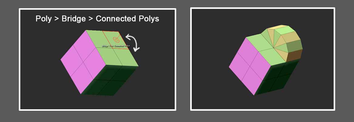
My contribution to this thread is probably very little and very basic to most but I thought I’d share some array and nanomesh things.

After you have created some random object and used a profile from the array presets if you turn off transpose in the array tab you can use the transpose
move line to manipulate the object further.
Untitled-1.jpg2.jpg5.jpg

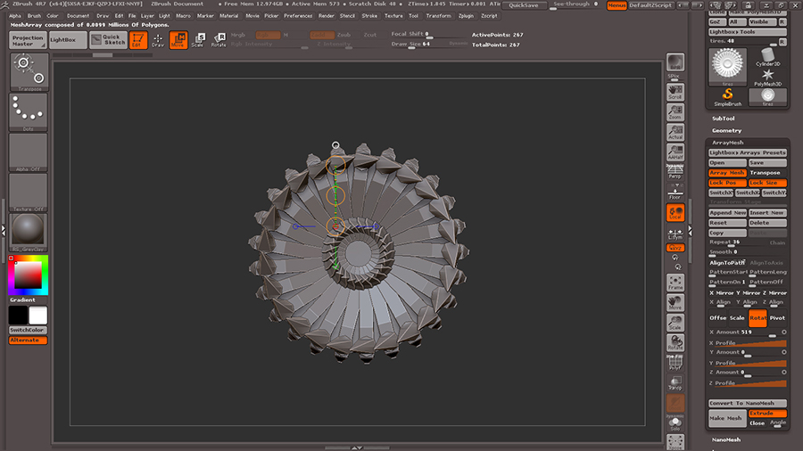
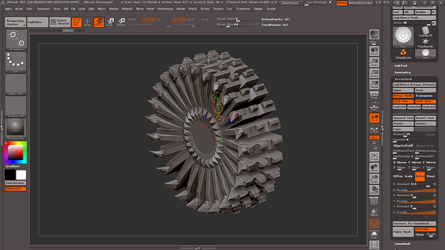
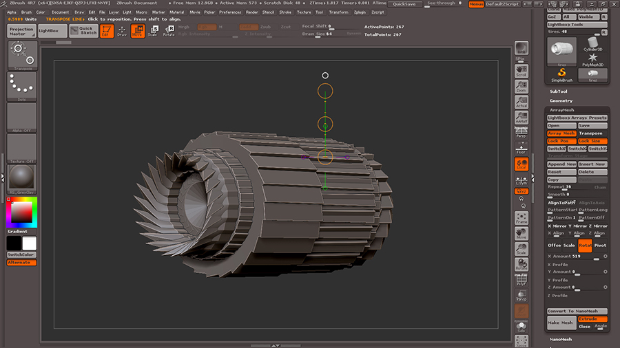
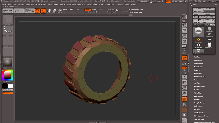
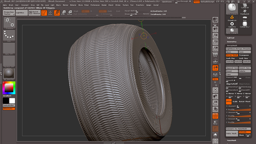
Some objects that in your head start out as something different after playing with the array mesh presets. I modeled a quick and dirty mudding
tire, mirrored it on the Y axis and pulled it out with the transpose line and applied the array tire prest with a high repeat.
Thus giving me something way different than what I planned, or as I like to refer to it “a happy surprise”.
3.jpg4.jpg

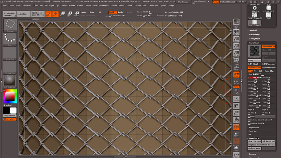
Now something I’m sure many thought when they seen nanomesh previewed, fish net, fence, etc. Here I modeled a quick net piece, made it an array mesh
then converted to nanomesh in array tab. In the nanomesh tab assigned it to the zmodeler brush, then set the polygon order of the brush to “insert nanomesh,
all polygons”. Play around with the rotation and size in the nanomesh tab to get best effect.
net 2.jpg

I know I can delete them and bring them back holding shift
???

One possibility is to delete the Edge Loops and make two new Edges.

One possibility is to delete the Edge Loops and make two new Edg
es.

just say you don’t know

A bit late on this
 I thought showing how to make the doghouse was a great way to show off the basics of ZModeler, so I made a tutorial image myself. Wasn’t able to get it uploaded until today, and I see that Spyndel already put up a great one.

Still, below is how I went about making it
 a little simpler I think. I hope it’s useful to see a slightly different way to go about modeling the same thing. ZModeler is really fantastic
 so much power tucked away in a rather efficient tool. Some rough edges, and some opportunities for workflow improvements, but it definitely seems to have nearly all of the key features I’d ever want to use for low res modeling!

tutimage.png

Something to be aware of is the snapping/merging feature of QMesh can cause some problems 
 try increasing or decreasing the brush size if you’re not getting the results you want. Also, sometimes it’s helpful to turn off attraction entirely in the modifiers section of the qmesh operation.

1 Like

just say you don’t know

Why i should say i don’t know?
Have you try to do this?
Or know you not how?

1.) Right click to one Edge > choose: Delete > choose: EdgeLoops Complete. = Then delete your Edge Loop comlete.
2.) Now again right click to once Edge > choose: Insert (RRRRRt! Not inset!) > choose: Single EdgeLoop = create your new, or two new straight EdgeLoop/s.

I know I can delete them and bring them back holding shift
???

I said I knew how to do that

Hey guys, was doing a quick vid for my Cert students and wanted to share. Thanks Spyndel for creating this thread! We definitely need more on this feature.

https://www.youtube.com/watch?v=9p-JYYgMahs&feature=youtu.be

Another possibility is:
Right click on a Point (EdgePoint not Edge) > choose: slide > choose: your axis where you want move that point > move that point, and with that your edge/s! ;o

*EDIT
And again another solution is:
Right click on a Point (you know smile) > choose: transpose > go out of the right click menu and click then another Point. And on this other Point you will receive the transpose tool and the rest of your model will be then masked. > Now you can with the middle circle of this transpose tool move your POINT (and hold shift during you move the point with the middle circle of the transpose tool) ;o)

Guys you are aware that ZBRUSH 4R7 has a manual with the explanation to EVERY SINGLE tool within it right
 ZBRUSH 4R7 What’s New GUIDE! I’ve read it TWICE

and GUYS ZMODELER CAN completely replace EVERY SINGLE TOOL IN ZBRUSH for HARDSURFACE
 I recommend you guys stop looking at CONFUSING tutorials from other artist PERSPECTIVES and just read the manual along with the tutorials posted on PIXOLOGICS webpage from Joseph
 Tutorials from multi-perspectives are like ONE BIG ARGUMENT inside my HEAD
 confusion

http://pixologic.com/zclassroom/homeroom/

also I recommend searching for hard-surface tuts in for 3DS MAX or MAYA and just doing them in ZBRUSH
 It’s all the same bro