ZBrushCentral

Z 2 CNC Sketchbook

Hello All,

I got a PocketNC a while back and I have been working out a consistent workflow from ZBrush to Fusion360 to a PocketNC desktop CNC 5 axis mill.

Fusion’s ability to import STL files directly into CAM without conversion to a T-Spline is new, and it still doesnt take full advantage of the 5 axis functionality as the 5 axis movements still want to follow T-Spline curves, but it get me to where I’m currently trying to go. And the PocketNC is a great toy to learn with.

Royal Ebony (Katalox) & 260 Brass
3 in diameter x .75 in depth
Stained with Graphite
17 hrs milling time
Detail level 0.025 in

First sculpture in a series titled “Dark Money”.

Attachments

8010b-b-sig.jpg

Harvey989725bit.jpg

IMG_0553b.jpg

Fusion_Cat2.jpg

1 Like

Very nice!! Would you mind sharing some images of your workflow, from ZBrush to TSpline and Fusion then CNC? I’m sure a lot of people would be happy to know more about what you are doing!

Hello Totyo,

That was my original intent.
I had a dozen images, and I guess it got too big, cause when I Previewed the post, it got hosed.

I may have time over the holiday to try again.

Thanx

Wow… I want custom Tokens too!!

I had been inspired by a Selwy post back in '12 where he used a company in Italy called 3DWood.
In '13 I used them for a project, and I was very satisfied with the final results.

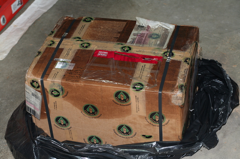
But there were some unforeseen awkward difficulties. My shipment got caught up in Customs for a month
because it had apparently come into contact with an angry bottle of olive oil.
box_oil.jpg
So I wanted another solution, closer to home. I had chosen 3DWood in the first place because it was so hard
to find anybody in the USA that would cnc anything beyond a sign. (2 or 3 axis cnc)
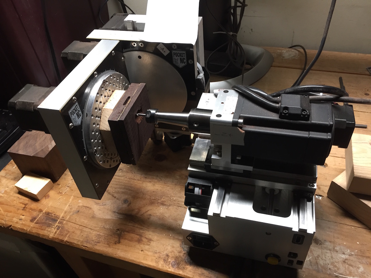
About that time PocketNC had a successful Kickstarter for a desktop 5-axis cnc. After they had shipped their
Kickstarter models, I became customer #020 for their public offerings.
zc_PocketNC_Stuck2.jpg

The PocketNC came with one year of Fusion360 (now its free until you make bank).
That has been the source of confusion for me over time.
Just because the PocketNC is 5-axis (but no Lathe), Fusion360 had no 5-axis features when I first got it.
Fusion360 now has Swarf and Multi-axis Contour, but they want T-Spline geometry to follow,
and that brings me to .stl and .obj files.

Originally, Fusion360 required all geometry for CNC CAM to be T-Splines, and it had a 10K face limit.
That posed a serious problem for exported ZBrush files. STL’s are chaotic, but even a structured OBJ file
would yield inconsistent results converting to T-Spline.

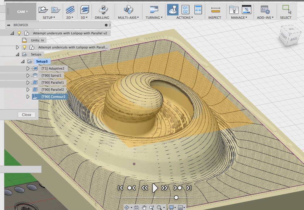
And then, even if you get a great T-Spline conversion, there might still be a gotchya. Here I threw at it
what I assumed was a simple small piece of geometry.
My Duael Designs Logo. As you can see in this Fusion360 simulation, there are areas under the lip that don’t get cut.
Fusion Customer Support took a look at this geometry and concluded that the code could not “see” under the lips that far.
duael_designs_logo_02d-1.png zc_Duael_Lollipop_bulge2.jpg

Now, as of May '17, you can bring .stl files directly into CAM in Fusion360, bypassing the need for
conversion to T-Spline, BUT, you still don’t get to use the 5-axis features because they still want
T-Spline curves to follow.
(Visualize yourself laying a pipe on train tracks and rolling it down the tracks. The pipe is your milling
drill bit and it cuts flat everything in between the tracks. That’s 5-axis Swarf. )

So, the geometry I have used here is a result of my struggle dealing with T-Spline geometry conversion
and my desire to use the 5 axis features, while continuing to work in ZBrush.
BlackScholes_Bool.jpg

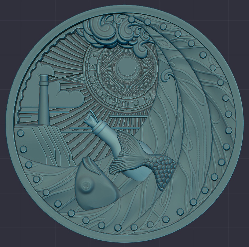
As you can see, it looks NURBS-ish, and that was my early solution to getting a T-Spline conversion
that was as useful as possible.
ie; resulting in complete curves along an edge that didn’t stop midway and go 90 degrees for no apparent reason.
It occurred to me that if Fusion360’s T-Spline conversion could recognize ZBrush Polygroups, there could be
a greater possibility of useful results, as it would be one extra layer of information.

But with the May '17 update, I decided to concentrate on my other concerns, and save the potential of T-Spline curves for later.
My goal was to cut multiple materials, Brass and hardwood, where the brass was sandwiched and would be revealed.
The reason for these materials was the Story. The Story of Dark Money, which I will get to later.
zc_ebony_brass_stock.jpg

As I am not using geometry that would allow for 5-Axis milling, what I am really doing is referred to as 3+2 milling.
While there are a dozen type of milling paths, my stl geometry required a small Ball End Mill using close
parallel passes for the Finish Pass.

I started cutting Machinable Wax first, as its easy on your tools, faster to cut, and shows you your detail level.
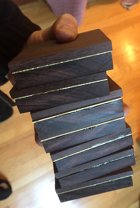
Once I felt I had a reasonable understanding of the cutting paths and milling bits, I switched to layered woods.
I didnt want to break bits hitting the metal wrong, so I practiced on wood, using a Maple veneer in between
Black Oak, with the veneer being 0.04in.
zc_machinablewaxpile2.jpg

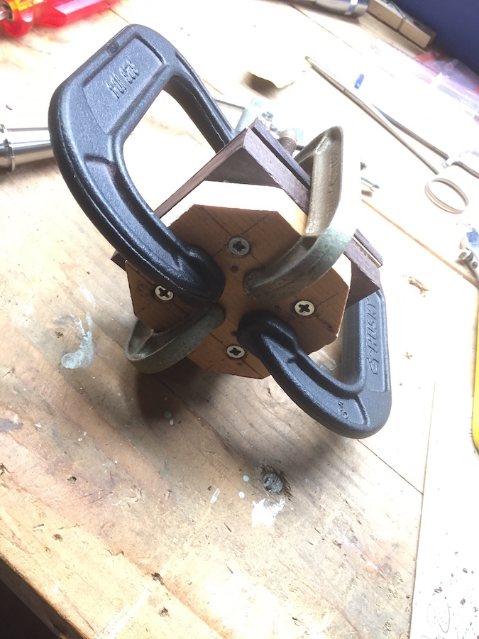
Wood being wood, there was a 0.01 possibility of error in a stack of 3 woods laminated, then screw
attached to a 1/2 piece of pine Sacrifice stock, which is screw mounted to an aluminum mounting plate,
courtesy of Randy Kopf. The error would be worse if you don’t pay serious attention to clamping.
zc_mount2.jpg zc_clamp_sacrifice2.jpg

I needed to make sure I could kiss the face of the brass with a Flat End Mill to get a polished surface,
and not go to deep thereby leaving enough metal for the engraving bit to not pass through the other side.
The veneer is 0.04, but the Brass will be 0.06, with the engraving bit being a Harvey #989725, which
has a 0.025 diameter tip.
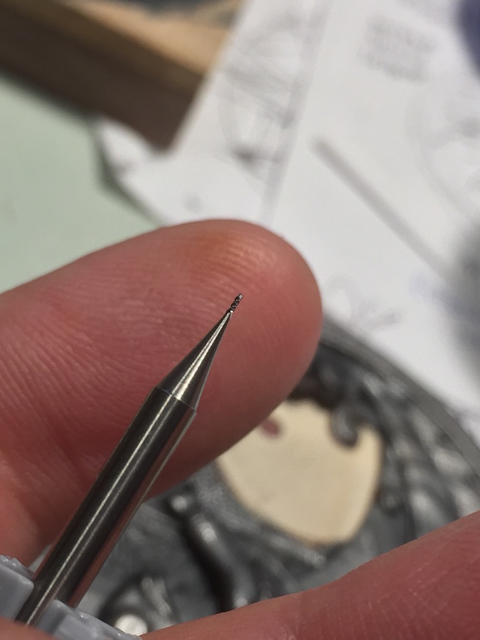
This bit is a Harvey #989715, with a ball tip diameter of 0.015, of which I broke two trying for the
ultimate in detail level, as this is the smallest bit I can find on planet Terra.
zc_metal_hit.jpg zc_harvey989715b.jpg

Gotta go for now. End of Part 1
~ more to follow ~

Thank you very much for sharing all these information, it’s super helpful! I would really love having access to a 5 axis CNC machine too! I don’t find the Pocket NC V2 that expensive for such hardware… but I don’t know where I would put that in my office! :slight_smile:
By the way, using ZRemesher to convert your model to a NURBS through TSpline is not possible for you? (I need to try through Fusion 360)

Totyo,

Thank you for the complements.

First, you dont want this in your office. I put mine in the garage.
Its’ loud, dangerous, and if you cut wood, some hardwoods can cause allergies over time, or immediate reactions to skin, eyes and lungs.

Second, if you really really want full 5-axis, prepare to shell out around 19K for MasterCAM.
There may be other alternatives, but MasterCAM is one of the Maya’s of CNC.

Play safe boys and girls.

zc_gear_rs3.jpg

Totyo,

ZRemesher is awesome, but its what the Fusion360 converter is “Looking For” that seems to be the issue.
If you have ever made a NURBS object, its very similar to a T-Spline in that the CURVES are the driving force in the geometry’s creation.
You could build your geometry to mimic a NURBS structure, as I had with my Duael Design logo I post previously in OBJ format.

Sometimes… this mimic geometry will result in a successful T-Spline conversion, but it is in no way consistent, even with the same geometry.
(This is my observation of the tool in early 2017. There have been many updates, and functionality may have changed)

Also, a full obj of a dense ZBrush file was still too big for Fusion360 (as of early '17) so I needed to send decimated stl files.
Decimated files tend to blow away any structure to the mesh that you would be able to bring over with the obj.
And stl’s aren’t Quads, which early Fusion360 also did not like.

SO now that Fusion360 can except an stl file without conversion to T-Spline, my workflow has centered around;

  1. Use ZBrush the way I want to work
  2. Export decimated stl files
  3. machine in 3+2, not 5 axis

Yes, I know how BREP in NURBS are working, but I’m not so familiar with TSpline. I’ll need to dig in.

And for such CNC machine, yes, I perfectly understand the constraint, it’s just something which fascinating me. But so far I already have enough to do with 3D printing.

Thank you again for sharing these information with us! (I’m sending you an email)

The Stock (what the CNC world refers to as the original prepared material, in this case a 3in x 3in x 0.81in laminated group of wood and metal) and the Sacrifice Stock (3x3x0.5in pine with cut corners) are both designed the way they are to solve mounting problems, and to allow cutting of the Stock material without the Spindle hitting anything. (The Spindle is the rotating part that holds the milling bit).

Sacrifice StockClearance.png

I start by cutting the backside before I screw mount the Stock to the Sacrifice Pine. Here I need to engrave the name of the work, my name and a slot for hanging the finished work on the wall. The placement of this engraving must be centered between the four screws that will mount the Ebony to the sacrifice pine. (Here I use the PocketNC vise, as its easier for this purpose)

BlackScholes_backside.jpg

Backside_fusion.png

4 screws pass thru the pine sacrifice stock to hold the Ebony, while 8 other screws hold the pine to the aluminum mounting plate. The sacrifice pine is there to give the spindle room to cut the full width of the Ebony, cutting into the pine, without hitting the mounting plate. You want to make sure that everything is as tight as possible so that there is no vibration in the Stock while it is being cut.

mountingHoles_0937.jpg

PocketNC provides a Fusion360 file of their machine which has a Origin Point (Dot in Blue Square). This represents the rotation center of the A and B tables. You will want to place your geometry (that which your are cutting to) and your stock (that which you are cutting from) onto the vise (if you use the PocketNC vise, I use a mounting plate by Randy Kopf) so that what you see in Fusion is what you get on the PocketNC. Your need for accuracy in placement may vary, but with my thin metal plate, I seek an accuracy of 0.01in for this placement of my geometry.

PocketNC_OriginPoint.jpg

There is more to do however to achieve accuracy per tool. There is a Tool Table (PocketNC), that needs to match your Tool Library (Fusion360). You only need to enter numerical data for each tool in the Fusion Tool Library, and you can get that data from the vendor website. For the Tool Table, you need to measure the physical distance of your mounted milling bit and the B-Table rotated 90 degrees vertical. You do this with a block of aluminum you are supplied with by PocketNC called the 1-2-3 Block. It’s a bit time consuming, and I won’t describe the entire process here. You can read their doc here.


Their newer model, v2, has a automatic tool length reader, so you no longer need to perform this task.

1-2-3Block.jpg

Once you have that out of the way, you can start playing with cutting paths, and I do mean playing. It’s kinda like Particle Systems, you play with sliders, hit GO, and wait. Look at the result, play, GO, wait, until you think you have something that is gonna work for you. Each path is designed for a different purpose. This is an Adaptive Clearing Pass, intended to remove large amounts of excess material as fast as possible, while staying a specified distance away from the intended Finished surface. It tends to look like a topographical map. You can run an animated Simulation that lets you see both the process and end result.

Z_path1.jpg
z_path2.jpg
z_path3.jpg

Once your paths are established, you need to address the Feeds & Speeds. These are the rotation speed of the milling bit, the translation speed in x,y,z, the amount of material Feed (removed) per tooth, and the hardness of the materials and cutting tool. It gets rather complicated, so much so that additional software like GWizard can be very helpful. The PocketNC is small, with a 10K RPM rotation limit, and 5/16 inch bit size limit, so you are not gonna blaze through aluminum un lubricated like you will see on Datron youtube videos. You can move quickly through wood, wax and synthetic materials, but the smaller your milling bit gets, the slower you need to translate. When I am cutting 260 (soft) Brass with my smallest bit, a 0.025in ball tip, it has a “Surface Speed” of 10 mm per min, and a “Feed Per Tooth” of 0.0006 mm. That is mind numbingly slow. Slightly faster than watching paint dry. It takes 8 hours to make the final engraving cut on the face of the Brass. (With knowledge I’m sure I can speed that up by 50%) You don’t have to stand in front of your machine for the entire time, but you can’t go fishing either. I’m thinking of getting a baby monitor so I can see it from my studio.

End of Part 2
~ more to follow ~

Attachments

backside_cut_0670.jpg

Great info.

How much does the pockeyNC cost ? (The best I could see was about $3500… but I’m sure the price goes up from there with the software and additional hardware)

I own and run a 4 axis cnc… I considered adding a 5th axis but it just became way too much trouble to do in order to unite it with an affordable 5th axis software. (So I gave up on that notion)

What are your times for machining pieces ?

I’m guessing the Gcode must be more lines of code and pretty large files (on a 5th axis)

Thank you for sharing !

DougE

Hello DougE,

The v2 of the PocketNC costs 4900$US
PocketNC v2

I would highly suggest the v2 as it has some awesome upgrades, like an automated tool length reader, Lathe, and a really cool Collet mount.
It also looks like the freakin Batmobile.

As this small machine does not have a Tool Changer like a bigger Hass and such,
the best thing is to buy as many Spindles as you have tools (milling bits).
The Spindles swap out really easy and fast, and lock down to their original position.
That’s 60$US per, but otherwise you would need to remove the tool from the spindle during a tool change,
and then figure out the new Tool Length Offset with the 1-2-3 Block I mentioned.
This would mean you might need to remove the entire stock if it is in the way.
I would need to do that. Way too much trouble.
So it’s just easier and more efficient to have a spindle for every tool.

Tools range in cost. Some are for softer stuff like wax, plastic, softwoods.
I buy mostly bits for “Non-Ferrous Metals” as in aluminum, brass and copper.
These are also necessary for the harder hardwoods.
I buy only (so far) 1/8 inch shank bits, so generally these small bits aren’t that expensive, 15$US to 30$US, but as you get really small tips, they cost around 50$US.
That is, if you buy from a known vendor like Harvey Tools.
You can get bits cheaper than that if you are less concerned about their manufacturing quality.

My G-Code can get to over 100K lines, but I have no idea if that big or not.

Thank you

DougE,

The Fusion360 Simulator can give you a rather accurate time estimate.
This is typical of my current times, some have been as long as 17hrs overall.
(This time represents All of these cuts, not just the one that is highlighted)
SImTime.jpg

I have been using Fusion360 because it is the only 5-axis software I can find on OSX, and it happens to be free.
PocketNC supports other software choices, but I don’t know all the prices.
http://www.pocketnc.com/post-processor-information/

Nice work Duael !!!

Here is a excerpt of a similar workflow I did http://desktopartisan.blogspot.com/2016/11/workflow-wrkflo.html

Below is 2D to 3D Work flow I used to create a necklace for my Girl.
It started with a 2D image I found on the internet. No idea who the author was but would like to meet them.
The image has a feel of “I’m chill, just don’t mess with me!”
Bear Growl 2x Scale.jpg
In Fusion I built a 3D Precise model using the 2D image as reference.
I did not have ZBrush. I am a hobbyist and full ZBrush was not in my budget.
Bear Growl Fusion 360 Precise Model.jpg
Part way along the process my daughter said “Nice Gummy Bear!” Well that was not the effect I was working for.
This was months of modeling as a precise modeler was not the right tool for this job.
Bear Design is close but missing eyes, teeth.jpg
I knew the model was seriously lacking FUR detail. Fortunately ZBrush Core just came out.
So I exported to ZBrush Core for intense FUR Texturing. This was done in one evening or about 2+ hours of work.
Bear Growl ZBrush.jpg
Then sent to Desk Proto for CNC CAM Tool Path creation.

Bear Growl DeskProto.jpg
Then machined a Wax Mold was machined on my Pocket NC Mill
Bear Growl Machined on Pocket NC.jpg
Finally the part was cast using PMC Clay from the Wax.
Precious Metal Clay looses some detail in the forming process using a mold. I was able to enunciate a moderate amount of detail into the “Green Form” before firing in a kiln.
I finally fired in a Kiln at 1600 degrees for 3 hours and blackened and polished the piece.

I could have got significantly greater detail in the final part if I used Lost Wax casting. But I did not want to take a chance of sending it out and having the design copied as this is a one off gift for my girl.
One year in the making. Could have been just a month had I used ZBrush to begin with :-\

Hey Randy,
Thanx for sharing.

Everybody, Randy is the maker of the aluminum mounting plate that I am using.
It’s so much easier for me to use than the PocketNC vise.
He has been extremely helpful in getting me up to speed, and helping me understand the little quirks.

(Back to our regularly scheduled programming)
What I want to attain is this, incredibly sharp and small detail, like that which is achieved in Guilloche, on the surface of my brass.


guilloche.png

Cutting (more like carving) with a Rose Engine creates clean smooth gutter sides, which is why it reflects light so nicely.
I’m not currently getting that smooth of a cut due to a mathematical result called Scallops.
A Scallop is a wave-like ridge in the finished surface, which is the result of using a round cutting edge while translating.
You can get a scallop from your “Stepover” setting. (Think of two bowling ball gutters next to each other).

surface_fin.gif

Closing your stepover distance can result in a smoother finish, at the obvious cost of time.

Scallop1.jpg

Or you can get scallops from Translating too fast, so the roundness of the cutting bit leaves a wave-like pattern along the cutting path.

scallops.jpg

It may also be caused by Chatter, where vibration frequency(s) play a part.

chatter.jpg

Both can be solved by slower Feed (translation) rates, at the cost of time.
(Stepover is not the problem for me here, as my detail engraving gutters are sized in Zbrush to be the size of the bit, so it will only cut once down the gutters path(s).)

But there is a Gotcha, as going too slow is not a good idea either. Increased friction creates heat and reduces tool life.
It can discolor materials as well, and I have already experienced the smell of burning wood from cutting too slow.
So there is this constant battle between my stock materials, soft metal and hard wood.
My bad for choosing to play with these two materials in such a crazy way.

Using this very small Harvey#989725, 0.025in Tapered Ball End Mill, I am already cutting the final fine detail at a disturbingly slow rate of 4 hrs.
What does that mean?
That the bit is traveling 30 meters in 4 hrs, and has a “Feed Per Tooth” of 0.00066mm, meaning, thats is how small a bite each cutting surface (flute) takes. And I am still getting scallops and/or chatter.
If I double that, the results should look better but at 8 hrs, that posses operational issues with regards to me not being able to do much else while the machine is operating.
As long as I have plenty to do in ZBrush, I can hang around and be productive, but the minute I need to do anything away from the studio, it becomes an On or Off choice for me.
The unfortunate thing about G-Code is that you can’t tell it to Start Over Where You Left Off (or where it failed last). You can’t Save and Reload in the middle of a cut. And you can’t just cut a paste g-code either (maybe if you are fluent) because if you cut out everything before it stopped, and tried to execute the remaining g-code, you would be missing the “approach” part of the code that would get the bit from “Home Position” (start) to where you left off (on the face of the stock).

One thing I have had to adapt to is the fact that there are real world consequences for software mistakes. In other words, when I worked in games, a mistake on my part, or a software failure, resulted in nothing more than lost time. (Actually, that can add up). However, when you are machining in CNC, or building a driverless car, people can get hurt when software goes wrong or is operated incorrectly.
When CNC-ing, you need to have a greater level of self confidence in your ability to operate the software/hardware. When you execute a .ngc file and your bit/spindle flies toward your stock, and then slows to a near halt 1 mm from the surface, you need to have the confidence that your .ngc code is correct, and that the bit is not going to Plunge into your stock deeper that you expected.

This image shows an accidental Plunge from a tapered ball End Mill thru hardwood into brass.

plunge_0934.jpg

Dont try this at home kids. Or if you do, practice your mistakes in wax.

plunge_0933.jpg

This shows another type of mistake.
I hadn’t tightened the spindle nut tight enough, so as the bit cut from wood to metal, the bit would bite the metal and get pulled out of the spindle, and therefore deeper into the stock.

plunge_0935.jpg

~ more later ~

More on the Scallops, and other issues.
There are three unsatisfactory results that can bee seen in this image.

The scalloping results in less than reflective engraved gutters, as it creates a kind of “noise” that disrupts the reflective surface, like a bump map. You can see the dull nature of the reflections in my photo, but the scalloping can be seen better in this video for the Faro35, which advertises itself as being a 5-axis CNC mill with Guilloche. (see minute 0:40)


As you can see, its awesome to watch true 5 axis movement in a machine, but it does leave scallops too.

  1. some parts were cut deeper. You can see a darker deeper border edge to the left and below of the number 2.
    My best guess as to why this happened is that something happened to the bit. If the bit chips, the cut will look different. However, after looking at the bit under magnification, its fine. No chips or breaks. Also, after looking at the “order” in which Fusion360 chooses to place the bit when making a cut, there is so much chaos in that process, it makes it impossible for me to get a visual indication of which parts of my engraving cuts are before and after these problem areas. (The Simulation feature in Fusion360 is not that easy to use if you need to zero in on a specific time or specific spot)

This image is of an unfinished cut of the brass face engraving, and you can get an idea of the random nature in which Fusion360 has chosen to place the bit to metal.

Fusion360 is not choosing to “follow” a curve, but in all fairness, with an imported stl file, it can’t. It probably could follow a curve if it was a T-Spline curve generated in Fusion. There may be an advantage for me to import most of my Zbrush file as an stl, but then create an additional part within Fusion360.

  1. the distance between some of these cuts is way off.
    The ZBrush file and the Boolean function generated a file where each gutter is equidistant from the other, as seen in this screen grab from Fusion360.
    But for some reason, some of these paths are cut in a manner that creates fat and thin islands.

At first, one might assume that this is the result of Tool Deflection. (From GWizard)

But Tool Deflection happens in the direction of the cutting path.
These Fat and Thin “islands” indicate that something was happening at 90 degrees from the path, or along the Z axis. As we saw before, if I don’t tighten the bit in the Tool Holder enough, it can get pulled out (and I assume, pushed back in)

However, when we look at the smile in the middle, it was cut late in the process, and shows no signs of any tool damage, incorrect depth, or mis-alignment.
So I am at a bit confused as to what is causing this.

(Side note: If you are wondering how and why the bit could not be tight enough in the Tool Holder when you are using tools like “wrenches” to tighten? You are still tightening by hand, because you can’t grip the other end with a tool. It’s round. The best you can do is mount the Tool Holder in the Spindle and use the allen wrench to hold the free wheeling spindle from moving. But that has a low level of torque.)

~more later~