ZBrushCentral

Too low contrast of displacement output

So I’m trying to output 4 displacement maps for a character (via multi-displacement ZPlugin), and I’m getting results that look to the naked eye to be almost completely grey (except for seam artifacting). Once I up the contrast in PS to about 90% I can make out my detailing. This is severely limiting the amount of detail though, as all the height information is being stored in only a fractional amount of the histogram.

I am trying to output the maps from the base subD level, with the original morph enabled. The DpSubPix doesn’t seem to make any difference (tried all values from 0-4).

Thanks for any replies, and I apologize if this has been covered already, but I couldn’t seem to find any existing threads that explained a problem similar to this so far.

unless you have a single point displaced far from the model zbrush will automaticly make the best use of the value scale available to 16bit grayscale files. Just because it isnt visible to the naked eye does not mean that the map does not carry the details you need. Pixolator discusses the tech of how the maps work and the value range here. It is an awesome thread chock full of good info. The details may be “crunshed” in the histogram because one area is displaced far beyond the rest either by design or by accident in the “stray point” case.

You can make sure the model does not have an offset or stray point (which will adversely affect map generation) by alt-clicking on the workspace and centering the model. If it seems offset or very far away then there is a single stray point. That can be fixed with thesetechniques.

Do you have issues when rendering the maps? The renderer will see all those values much different than they are displayed so you may not have a problem after all.

Keep us posted : )

Scott

Well, the only problem because of this issue is that I’d have to increase the contrast of the maps so much. I naturally assume that the end quality of the displacement suffered because of this. I’m sure for anything but a close-up shot wouldn’t really be noticable, but it’s frustrating thinking that the level of detail achieved in ZBrush wouldn’t be exactly bang-on what would be seen in MR. Maybe I’m just a quality nerd…

I’ve actually just now solved this problem, and the reason for it is kind of long-winded and obscure. For starters, the reason my maps were so contrasted was because of the artifacting happening along the UV borders. Since the color range of these artifacts is so severe (0-255), the displacement values pale in comparison, and show up as very indistinguishable shades of grey. So now the problem became the artifacts themselves; eliminate UV seam artifacts, and the map range would only include the highest and lowest elevations of the displacement.

For some reason up until now, when generating my maps with the multi-displacement ZPlugin, I only got three of the four maps that make up the character. So what I was doing, was generating the first three, then doing a second pass for the last map (via hiding the rest). The problem of doing that, was when it generated the maps in two passes, it counted the missing group(s) as a big-ass hole, and since ZBrush doesn’t like holes in the geo, it resulted in garish artifacts all over the seams of the maps where they would meet each other.

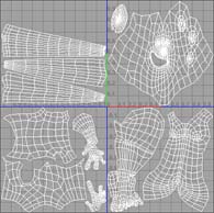
Now the reason it was only doing three out of the four, is because I had two maps in the ‘same’ place (as far as ZBrush is concerned). See attached .jpg

My uv groups were arranged in both U and V:

group 1 - U = 0 to 1, V = 0 to 1
group 2 - U = 0 to 1, V = -1 to 0
group 3 - U = -1 to 0, V = -1 to 0
group 4 - U = -1 to 0, V = 0 to 1

group 2 and 4 were both being labeled as plate ‘-1’ in the progress window as they were generated (which is why I had to do them seperately)

Zbrush likes UV groups arranged straight along the U axis. If you stack them in the V axis it seems to get confused. So I re-arranged the groups to sit side by side along U. Once the groups were all arranged like that, the multi-displace ZPlugin exported all four maps at once. When it did that, there were no holes in the mesh. No holes in the mesh meant no artifacts along the borders, and no artifacts along the borders meant nice crisp, contrasted displacement maps.

So always make sure if you’re using multiple UV groups to arrange them along the U axis.

Attachments

UVs.jpg

Im glad it worked out for you!
The artifacts at the borders are outside the UV shell and should have no effect on the map generation. At least that how I understand the maps from Zbrush. That is also provided we are talking about the same artifacts, I assume you mean the black and white jaggies that appear just outside the edges of the maps?

Out of curiousity, when you polygroup the mesh does the same color get applied to the sections that were in the negative regions?

Scott

No, the UV groups were all colored differently (albeit only slightly different shades of green, heh).

After numerous tests, I’ve found that the artifacts do in fact influence displacement map generation. Another way I’ve found that UV seam artifacts (yes, we’re talking about the same ones) appear is if you set your extendBorder option too high. It seems for my test that anything after 3 pixels extended will manifest artifacting in the map, and subsequently cause the displacement info to be crunched down to a very small range.

I’m continuing to test this theory out, but my advice as of now to anyone reading is to not set your map to extend the edge by too much (which I of course, did constantly up until now).

But please share any info you’re come across that might prove me wrong; I like to get my hands on any material that I can. I’m still pretty new to all this noise.

Thats a really interesting discovery, thanks for posting the findings here! Let us know if you come up with anything else on this.

Where is the extend border option in Zbrush? I cannot seem to find it : )

Scott

Alright (big sigh) I have NO idea what I’m talking about. Scratch everything that I’ve said about artifacting so far.

For some reason, when I was doing all this testing, I was viewing the maps in Ifranview after they exported. I guess Ifranview does some sort of auto-levels-style adjust to greyscale images when you view them, because they show up nice and contrasted. When I load my new maps in photoshop, they’re still just as de-contrasted as the original ones. Except more so now. Somehow.

So I’m back to manually adjusting the contast in PS after they export. Which makes me nervous, cause when you mess with this crap by hand, you can screw up the map midpoint, and get seaming on the final render (in a proper 3D program). Also when the info gets crushed down so low, even in a nice format like 16-bit .tif, you’re likely to get banding when you bring it back into the visual range. Agghh. Every day at work there’s a new show-stopping problem for me that ZBrush vomits onto my workflow.

Back to my original question then. Does anyone know why I’m getting these low-contrast maps?

It is possible that the program you are using to view th emaps has an autoleveling feature that shifts your values. Photoshop does this make absolutely sure you turn off color managment before you open the map Edit>>Color Settings

The maps should never be hand adjusted, like I posted at first Zbrush makes full use of the range of values and just because you dont see the contrast does not mean that the renderer does not. The computer is FAR more sensitive to the values than the human eye.

Try a render test with the maps you have. Also check the links I posted earlier about stray points. If you dont have a very misplaced mesh and you have a very washed out map that is likely the cause. Check into the Pixolator thread on map values too, its the start for anyone who wants to really dig into how zbrush calculates the maps. Check those links.

Scott

Here’s a quick and easy way to check to see if there’s a problem with your map:

With the map selected in the Alpha palette, press Alpha>Crop And Fill.

Look at the canvas. Are all the details plainly visible? If so, then there’s nothing at all wrong with the map. All of the detail IS there, and the computer can easily see it even if your eyes can’t.

Displacement maps are output as 16 bit images. This is a LOT more shades of gray than the human eye can distinguish between. ZBrush will not try to artificially “stretch” the grayscale values so that you get an image that makes full use of the range between pure black and pure white. Why? Because that would mean interpolation. Pretty much the same kind of interpolation that you see when you take an image and magnify it. You don’t really get more detail; you actually get a degradation of the existing detail. ZBrush calculates the exact values that are necessary to exactly reproduce the details on your mesh; no more and no less. If you don’t run your map through any kind of processing that strips it down to 8 bits, and your rendering engine can actually read all 16 bits of data, then it will be able to see all the detail in your map and give you a perfect render.

In other words: Make sure that your rendering engine has true 16 bit support. And be VERY careful about opening your map in any image editing software. Photoshop, for example, is notorious for doing things like Color Management (which shifts the values so that zero displacement is no longer 50% gray) or stripping the image down to only 8 bits.

Oh cool, thanks for the reply Aurick! I was totally mistaken on the way zbrush uses the 16 bit range : )
Always learning : )

Scott

Yeah, I guess I’m resigned to just multiplying the displacement in Maya by a few hundred fold.

Just seems ridiculous though, and it would be nice to have a map that you could actually see different values in (my eyes aren’t 16-bit).

Thanks for all the replies everyone.