OK. As you have probably already figured out, many of the methods you might use to draw out meshes in a sequence don’t actually draw the shapes out end to end, but at regular intervals. When they are scaled, they scale towards center, and increase the space between the meshes. What you would need to do is increase the frequency of the meshes at the same time as you are scaling them down.
Curve strokes can’t do this to the best of my knowledge. The “Size” modifier there is for tubular stroke types. The intervals are determined by brush size and Lazy Mouse Lazy Step.
You can do this with Arrays, though, with a bit of experimentation.
Click here for the process--collapsed for readability
-
Load the mesh you would like to array. Switch on Floor Mode to visualize all the axes. Make sure the grid elevation is set to zero (Draw menu > Floor section > ElV slider). Shift-Rotate the screen plane (camera) to lock the view to the plane you want to work against.
-
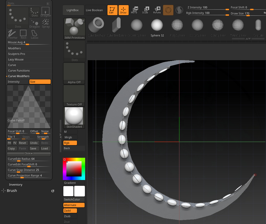
Scale your root mesh as desired. This will be the largest “pearl” in the chain.
-
Activate Array Mesh. Make sure that “Transpose” is enabled in the Array Mesh menu.
-
Transpose mode works with the transpose action lines. It doesn’t work with Gizmo. Disable Gizmo (Y by default on keyboard) to activate Transpose mode.
I find arrays much easier to create with the transpose controls. You will need to understand the way that Action Lines work, and which circles to drag on in which mode to achieve the effect you want.
Briefly:
-
In Move mode, dragging on the inside of middle circle will move the target around the screen plane.
-
In scale mode, you can scale the target by dragging on the middle of the end circle.
-
In rotate mode, the action line works like a lever, where you rotate the target around whatever point the line starts at by dragging on the end.
Normally you can draw action lines anywhere on your geometry, but in Array Mode they will be anchored to the Pivot, which is a light yellow circle that can be moved around independently.
-
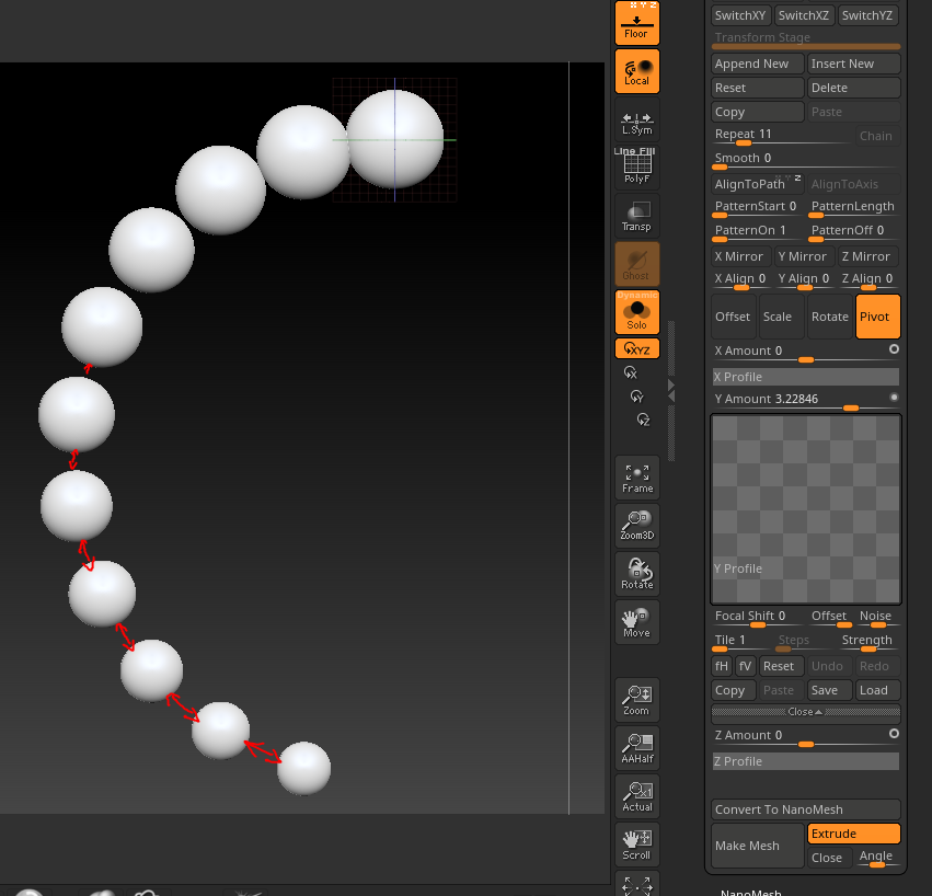
With Transpose Mode active, set the number of repetitions you’d like to target (Repeat slider, maybe ten or so to start) in the Array menu.
-
Now, In Move mode (W) drag the end point of the array to the general location you’d like the curve to end. (Middle circle on transpose line moves around the screen plane).
-
In Scale mode (E), scale the end point to the desired size you’d like to end up at (drag on last circle of scale mode action line). This will be the last time you have to work in Scale mode, unless you’d like to change the size of the final “pearl” again.
-
Now, in any mode, drag the light yellow pivot circle around until the line starts to become the curve that you want. This is the control that will have the most effect on differences in spacing between the pearls.
-
Switch to Rotate ( R ) mode to correct the shape of the curve as it is changed by moving the pivot around. Rotate the end point by dragging on the farthest circle from the pivot.
So basically here you just need to find the right balance between offset (Move mode), Pivot (yellow circle), rotation (rotate mode), scale, and number of reps. As you change one thing, the others will need to be adjusted to compensate.
If the meshes start to separate at the top or bottom of the curve, move the Pivot in that direction to adjust the spacing, and then correct the shape of the curve with a combination of Move and Rotation. Eventually you’ll find the right balance.
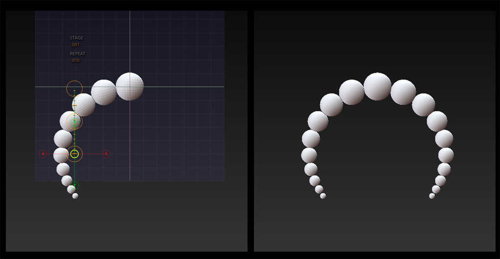
I only created half of the curve and then performed a Mirror and Weld (Tool > Geometry> Modify Topology> Mirror and Weld) once I had converted the array into live geometry (Make Mesh). This is why I enabled the floor grid so I could see the mirror planes. You could create a more advanced array if you really wanted to.
Click for notes about Nanomesh--collapsed for readability
The answer to this is NanoMesh, or at least it’s supposed to be. With Nanomesh you can control the placement of meshes by manipulating the topology of a target or control mesh. However, I’m not certain if the feature that would make this much easier is functioning correctly.
There is an option called “Fit” in the Nanomesh menu that is supposed to scale the nanos to the bounds of the target polygon without altering its shape. I have never been able to get this to work though and I can detect no difference from the “Fill” function. If it did work, it would be fairly easy to draw in a string of pearls along a control mesh that tapers towards the end, scaling the pearls at the same time. For now it appears you have to work in Proportional mode to keep the Nanos from distorting.
You can still make it work, but it requires a bit of artistry. I would do this by drawing out a curve on the surface of the character that I want the necklace to conform to. I would draw out a small control mesh by applying a Curve Tube Snap brush to draw a solid tube on the curve at low-ish poly density. Now I have a control object with loops spaced at regular intervals that I can manipulate for nano placement. With ZModeler I would start deleting loops where I’d like the pearls to start scaling up, and slide the edge loops around to create increasingly larger gaps between the larger pearls to give them room to be scaled upwards without overlap.
Once the spacing is correct you could:
-
Fast: Run an Inflate brush with a wide radius and a low intensity over the pearls to scale them up. The low intensity of the brush should make it forgiving to work with, and easy to gradually increase the size of the pearls along the line.
-
Precise: Adjust the size of the pearls with Gizmo. You can hold down shift to scale in constrained increments, so you can know that each pearl is X units larger than the next.