ZBrushCentral

Branched zspheres to mesh with specific profile

Hi all,

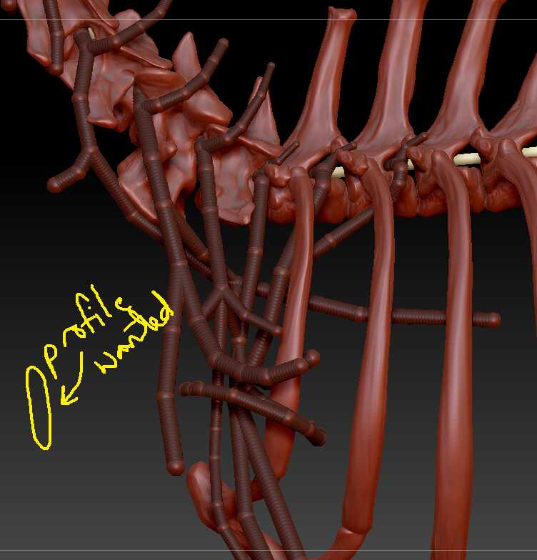
I have created this fairly complex network of zsphere subtools.
zspheres

They eventually will be anatomical nerves, so I’d like to turn them into geometry with an oval, rather than a circular profile (like a nerve would have in real life).

I was thinking of doing it with curve helper plugin and applying an IMM brush with the profile that I want, but it seems this isn’t possible for branched zsphere curves.

It seems like my main option then is just to convert to normal geometry using adaptive skin and then try and use a brush to smooth out the profile?

I am wondering if any of you might have some neat tricks for creating an oval profile on the zsphere curve that might save me a lot of time?

Cheers

Hello @arumiat

It should be, though it depends on your expectations. You can use the Curve Helper plugin then click on the resulting curve with an IMM Curve Stroke brush, and it will draw geometry along all the branching curves. What it will not do is to join all those branching curves–there will be gaps that you will need to manually close. A curve stroke can only ever draw geometry along a single curve from start to finish. Sometimes the curves can overlap, but they will never be fused into a single mesh.


Curve Tube strokes would be ideal here, because if you decrease their ZIntensity down from 100, they will naturally tend to assume a squashed oval shape. No need to fuss with custom IMM.


I personally think the easiest way to work with complex curves is to sculpt a target mesh in the shape you want your curves to follow, and use a tool like the Topology brush to draw out exactly the curves that you want along the surface, then click on those curves with an IMM Curve brush or something like Curve Multi Tubes to draw geometry along all the curves at once. If you do this with a sub-100 ZIntensity, the geometry will be “squashed”.

This will end up with a network of intersecting and overlapping, but not fused, oval tubes. They can then be fused with Live Boolean or Remesh by Union, and ZRemeshed to clean and simplify the topology to make it easier to work with.


Likewise if your target mesh is high enough resolution, you could draw the tubes as mask lines on the surface, then Extract them with the Subtool> Mesh Extract function. This will create a single unified mesh that can also then be cleaned and simplified as above. The mesh could be deformed or inflated as desired.


If you want to derive the geometry from the ZSpheres directly, you can attempt to use magnet spheres to distort the shape of the generated geometry, but I have to think most of the previous options mentioned would be easier.


Good luck!
2 Likes

I used this trick on the ZeeZoo Cat - Curve Helper, Curve Tubes with Zintensity at 60, followed by Dynamesh & then ZRemesher.

A bit of clean up using Sculptris Pro before ZRemeshing should give good results, I think.

1 Like

@arumiat Another option is to create oval shaped connector and joint meshes and then replace the spherical connector and joint mesh during creation of the ZSphere rig. See this video ZSphere Insert Connector Mesh That’s how the Mannequins and ZeeZoo rigs have different shaped joints and connectors.

1 Like

You are all extremely helpful thank you :slight_smile:

I tried going with the

  • copy zsphere chain
  • create curve
  • apply CurveTube

This sets me up well except for two things

  1. the curve often is orientated along it’s axis 90 degrees away from how I would like it. I have tried twisting using the blue circle that appears on hovering over the curve & then holding ctrl, but it gives weird local or general results without seeming consistency?

  2. if I activate symmetry and try modify the curve (as the model is symmetrical and the nerves exist on both sides so I want to manipulate both sides), it wants to create a new curve, rather than just modifying the one that is there? I’ve tried playing with the settings but no luck.

If I am missing something obvious for the above would be great to hear any possible solutions.

curves symmetry

PS @marcus_civis was your zeezoo cat a tutorial or similar? I searched on Youtube & these forums but didn’t find it if so !

@arumiat

ZeeZoo cat is a Zsphere mannequin found in Lightbox:Project:ZeeZoo.

For orientation, it might be easier to deal with it at the ZSphere level. Click and rotate the joints, rather than the links. Check the orientation by flipping back and forth with Preview and Classic skinning, density 1, Dynamesh 0 since the chain of spheres will appear as a square cross section tube.

As I suggested previously replace the connector with your own shape. You only need to replace the first connector for each new branch starting at the root Zsphere. Every connector created along each unique branch inherits the new connector shape. Try it with the Polystar3D as a quick check. Since your unique shape will have the non-circular profile you want you can see it’s orientation immediately without having to preview over and over again. Simply rotate the joint as you like after placing the sphere. You can even replace the joint shape if that makes any sense for your purpose.

Zsphere’s work with symmetry and so would resolve that problem. I thought curves did too so I’m not sure what problem your seeing in this regard.

Anyway it’s ZBrush so there are lots of options for getting the job done.

hth

1 Like

Thank you @tobor8man

For orientation, it might be easier to deal with it at the ZSphere level. Click and rotate the joints, rather than the links. Check the orientation by flipping back and forth with Preview and Classic skinning, density 1, Dynamesh 0 since the chain of spheres will appear as a square cross section tube.

I think I am encountering a bug as the zpsheres have the same orientation - and as soon as I click on the curve with the IMM mesh applied, everything straightens out. The only issue is that I can’t manipulate with symmetry on as it just generates a new mesh each time - I imagine a bug as well, if this is supposed to work

As I suggested previously replace the connector with your own shape. You only need to replace the first connector for each new branch starting at the root Zsphere. Every connector created along each unique branch inherits the new connector shape. Try it with the Polystar3D as a quick check. Since your unique shape will have the non-circular profile you want you can see it’s orientation immediately without having to preview over and over again. Simply rotate the joint as you like after placing the sphere. You can even replace the joint shape if that makes any sense for your purpose.

By selecting the root zsphere and applying connector mesh with the kind of profile I want, I wasn’t able to get all of the zsphere joints replaced - and I get this effect where it will be tricky to connect the connector meshes anyway because of all the acute angles, but I appreciate pointing this method out to me

this.PNG