Hello artists, would anybody have a strategy to design a shape like this 100% inside zbrush? thanks so much,
Hello artists, would anybody have a strategy to design a shape like this 100% inside zbrush? thanks so much,
Hello!
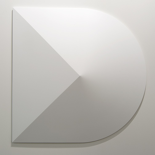
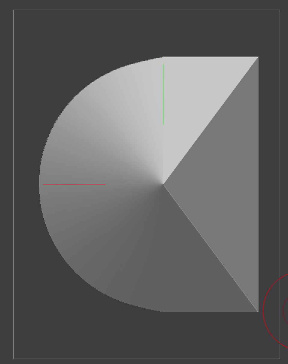
It depends on how we interpret the image. It looks mostly like a semi-conical object to me, which is pretty straight forward, but it could also be interpreted as semi-spherical if you squint a bit. In the case of the latter that would result in an impossible shape–if the rounded portion has a curvature to the surface, then the edges of the triangular plane will also be curved one way or another, and the best we could do is to make the shape look correct from certain angles.
So assuming semi-conical, this is pretty easy to do with some low poly modeling. A low poly approach would give you a very clean, flexible, and editable mesh to work with. Though it is far from the only way to do it, I do think this is the cleanest way.
The key to working with low poly, is to keep the topology as simple as possible, and never add more geometry unless you need it to define the shape. The simpler your topology, the easier it will be to control curves without distortion.
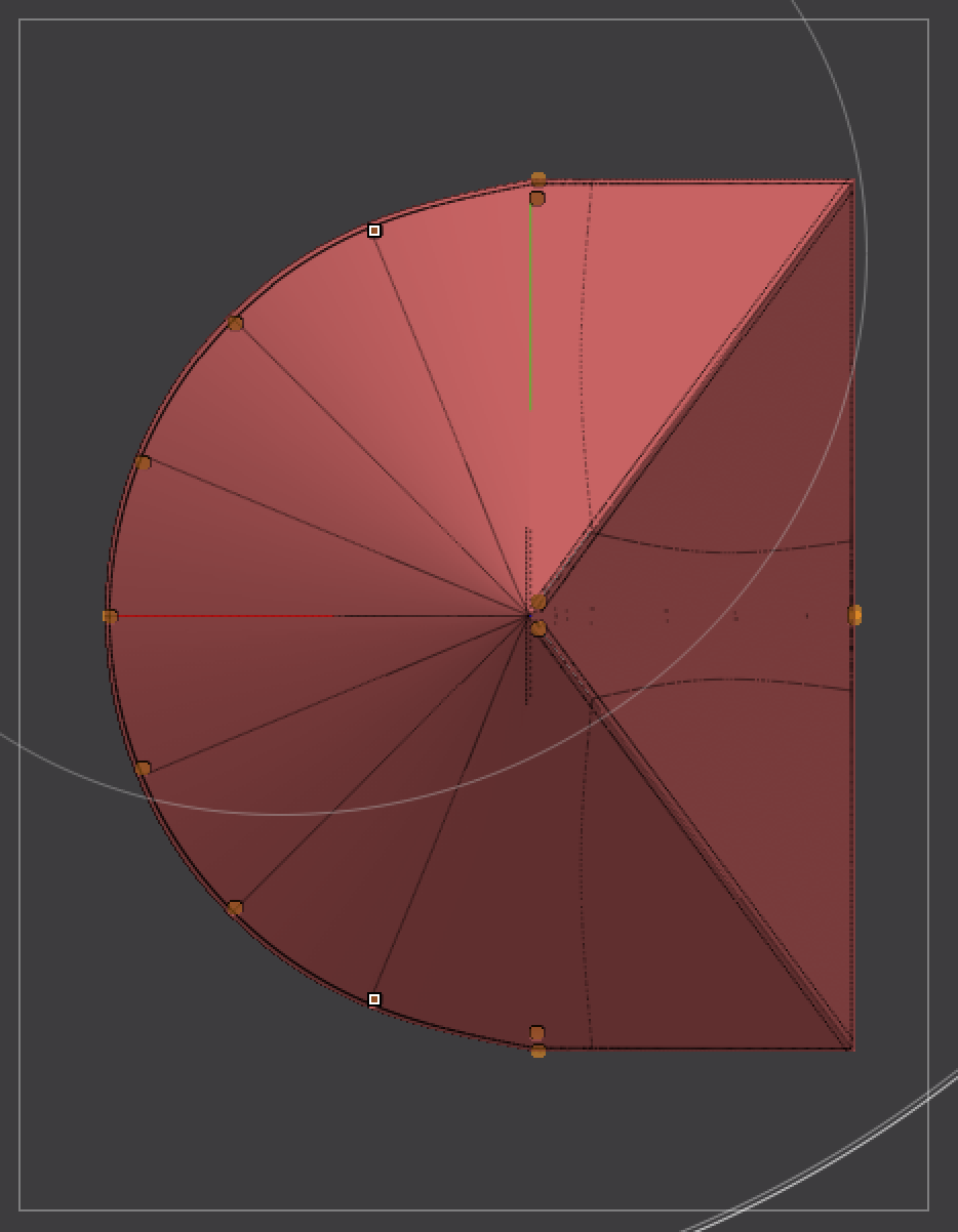
I’m using a Gizmo conical primitive here, ZModeler to add and remove geometry and add crease tags, masking to protect the mesh from Zmodeler deleting points I don’t want it to as well as to isolate certain points so I can move/transform them with Gizmo. I’m also using Mirror and Weld to reflect changes I make on one side to the other for a mechanically symmetrical shape. At the end I also inserted some partial edge loops on both sides to reinforce the points where the curve transitions to a straight line and keep them from curving prematurely. I’m using dynamic subdivision to preview the subdivided shape, while keeping the mesh low poly as I work.
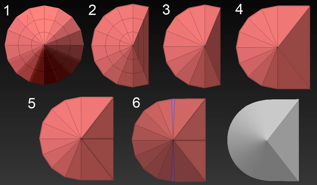
Rather than make assumptions about your level of Zbrush expertise, I have numbered the various stages, and you can ask me any questions you have about what I’m doing in each.
Good luck!
Thank you so much for your response. That is super helpful, as I was in a dead end looking into a high poly solution, trying to clip a high poly cone with a boolean cube rotated 45 degrees. I like your solution, except I am struggling to go from 2 to 3 in your helpful steps? I am not so good with zmodeler. I have been trying to delete these 2 vertical edges, they wont go away.
Thanks again!
Re: High Poly Approach.
If you dont want to learn ZModeler, I would recommend using the Live Boolean feature to make cuts with a high poly approach. This will let you line up a cut interactively in real time, and preview it before it is made.
Re: Low Poly question.
Ok, so what I’m doing there is basically just using the Edge > Insert Edge Loop > Single Edge loop function. It inserts an edge loop, or if Alt is held, it will instead delete a loop. I just went around and eliminated loops that were not contributing to my shape. You can set the Point and Poly modes in ZModeler to “Do Nothing” if you don’t want to accidentally perform an action on anything but the edges.
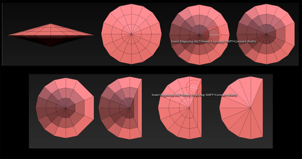
One thing I forgot to mention, is that I actually applied a quick Mirror and Weld to the object, to mirror the geometry on both sides. This is because Zmodeler can get a little confused as to what actually constitutes an edge loop when multi-spoke poles are involved, and this will help it to avoid making weird decisions about what to delete. There are lots of ways to get there–you could just create a quick sphere instead, and delete all the horizontal edge loops aside from the mid line, for instance. You can delete or flatten any excess geometry after you’re done.
Notice my masking. Because of that pole you will have to mask the center ring of polygons to keep ZModeler from deleting more than you intended.
[EDIT]
Sorry, cant post consectutive replies, so had to crowbar this into the previous post. If you’re interested in the premium version of this approach that is 100% machine perfect with no eyeballing, as well as simpler if one is proficient, I worked that up here. The only reason it looks complicated is because of the extensive illustration. The downside is that it requires you to learn even more program features, which is why I avoided it at first.
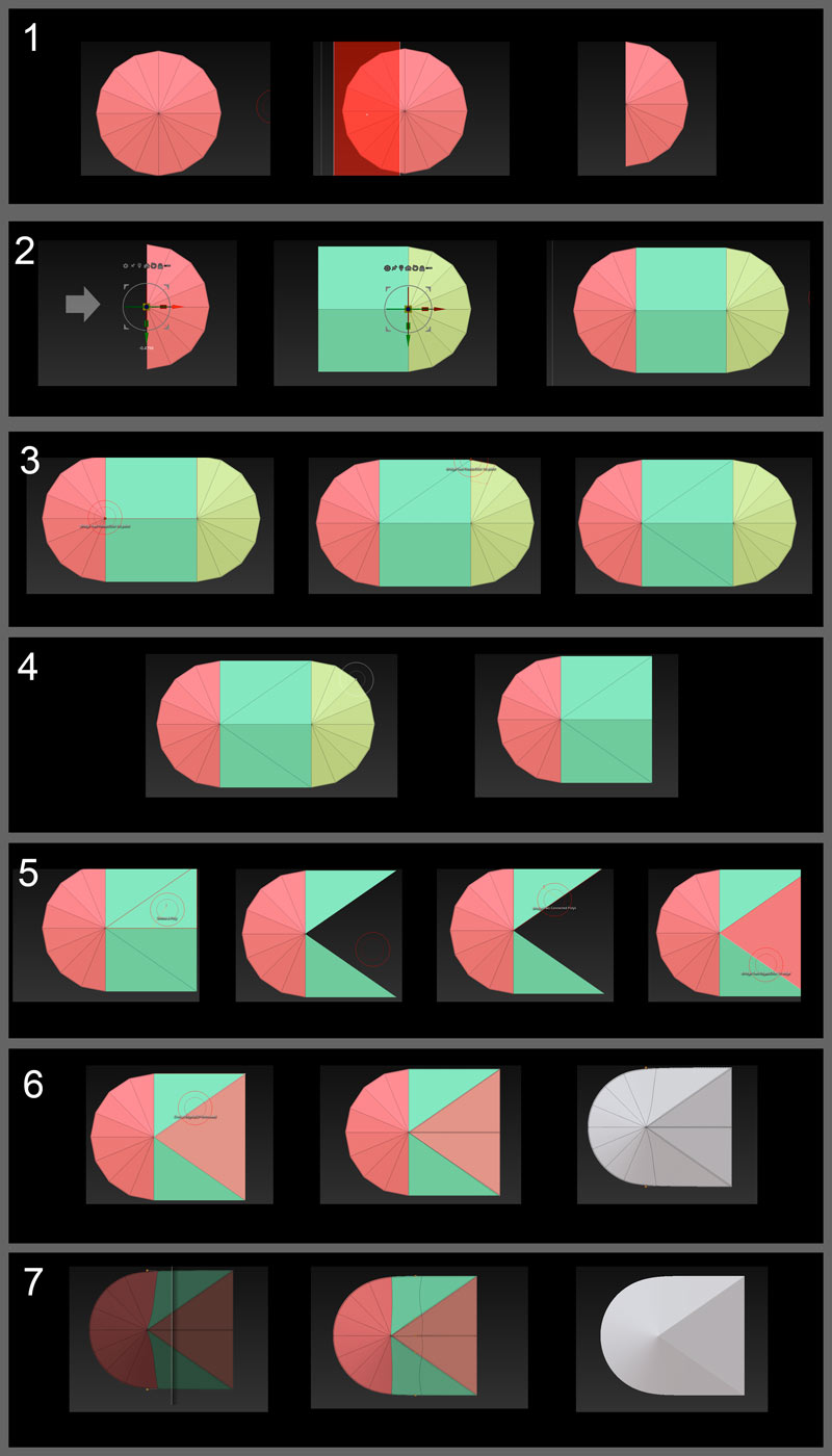
Move the visible half to the right with Gizmo. There are at least a half dozen ways to extrude polygons in ZB, but the easiest thing to do in this situation is to use Tool > Geometry >Edge Loop> Edge Loop. This will extrude polygons connecting the half we just moved to the hidden half, which you can now un-hide. The result is a bit of a capsule shape.
ZModeler > Point > Bridge > Two Points. Draw the diagonal in the resulting large polygon. Repeat the operation below OR Mirror and Weld along appropriate Axis OR work with symmetry enabled.
Hide the right half of the cone, which should be simple because it’s a separate polygroup ( you may have to shift-ctrl click directly on the verts). Delete it with Tool > Geometry> Modify Topology > Delete Hidden OR with ZModeler > Polygon > Delete > Polygroup Island (while not hidden). Have a care not to inadvertently Ctrl-Z during the next operation, as this will UN-delete your hidden mesh portion which may go unnoticed and cause issues.
ZModeler > Polygon > Delete > Single Polygon. Remove the triangular plane polygons. Fill them back in with ZModeler > Edge> Bridge > Edges. Click each edge in turn, and this will create a new plane directly between the edges. OR simply delete the center edge and point with the ZModeler Edge and Point Delete actions. You will have to do the edge first and then the point.
Use the ZModeler> Edge> Crease action to crease the triangular plane edges, as well as the perimeter of the shape. Use Tool> Geometry> Mirror and Weld along the appropriate axis to create a new centerline in the triangular plane which also needs to be creased in order to keep the triangle tip from drifting to the right when subdivided.
By previewing the mesh with Dynamic Subdivision, we can see what it will look like subdivided without actually altering our topology. Use this to see that the creases are all in place (no soft edges that should be hard).
I promise you it’s all very simple once you’re actually familiar with the tools 
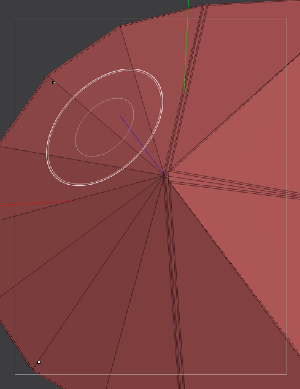
this is superb and vastly exceeds my expectations on this forum. I had only read your second (out of 3) replies so I managed to do this (attached, sorry for the huge attachments), which is not perfect yet is close (Dynamic subdiv flat 0 and smooth 7). I still have uncontrolled edge loops near the center and a visible edge at the ends of the half circle but I now know I need a serious learning session of zmodeler features.
Also I am not clear re low poly masking: when the poly is mid grey as opposed to dark grey, is it actually masked or not?
I am so happy to be now about to read your 3rd reply. Thanks again for the detailed work!
Crease tags can be overly severe and tricky to use when there is a mix of curved surfaces and hard edges to your object. Creases that end at the wrong point on a curved surface can create visible edges or artifacts. This is why I used additional, uncreased geometry to reinforce those points, rather than a crease. Two edges moved close together can do the same job as a crease for the purpose of subdividing, yet allow for finer control for semi-soft edges.
Learning to manipulate the quirks of Catmull-Clark subdivision is just basic modeling experience, not any deficiency in Zbrush training. You pick it up by doing.
This is just the way that Zbrush displays polygons in which only some of the verts are masked. It wouldn’t be very noticeable at high poly, but the large polygon size at low poly makes it much more prominent. Just focus on getting the points you need masked. Most operations in Zbrush are based on points, not polygons.