Hello I watched the tutorial with the snakes and I was wondering if those IMM are available in Zbrush somewhere couse I cannot find, or perhaps downloadable freely somehwere? Or Perhaps not at all available?
thanks for any answer.
Hello I watched the tutorial with the snakes and I was wondering if those IMM are available in Zbrush somewhere couse I cannot find, or perhaps downloadable freely somehwere? Or Perhaps not at all available?
thanks for any answer.
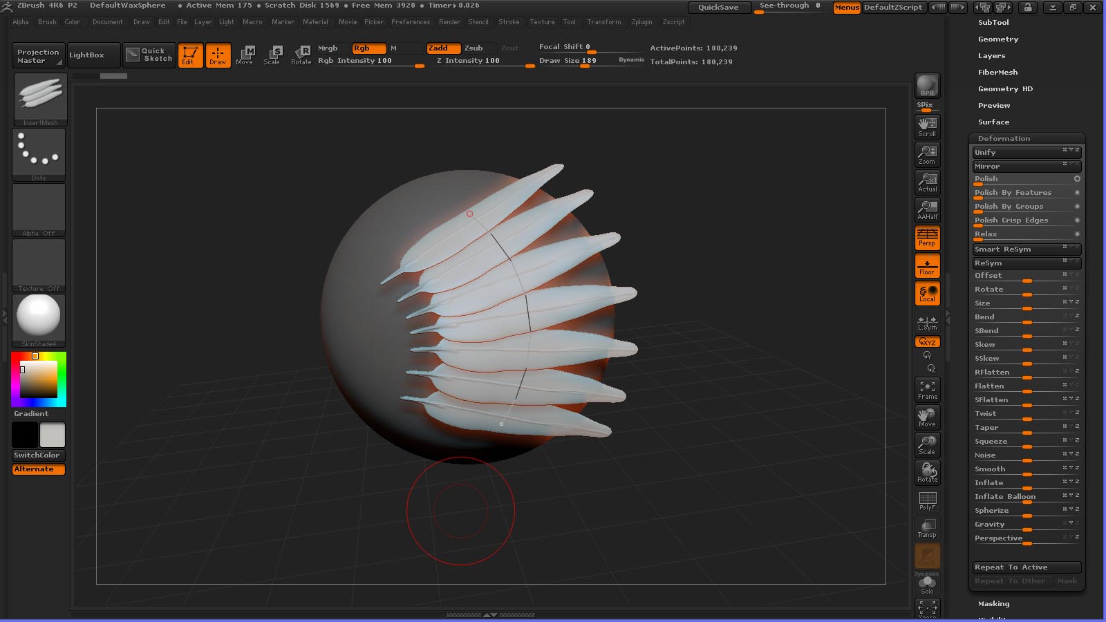
I am looking to make a feathers Curve Insert Mesh brush, I am part way there, but the brush that I have anchors each feather on to the curve by the middle of the object and I would like it if this could be anchored by the root of the feather - is there a way to achieve this? Thanks for any answers.
http://docs.pixologic.com/user-guide/3d-modeling/sculpting/sculpting-brushes/insert-mesh/creating-imms/ See creating.
Thanks for the prompt reply - I can see how to change the orientation, but not the “anchor point”, it seems to always select the centre of the object, which in many cases would be fine, but for this case an anchor point near the end of the object (on the “root” of the feather) is what I would ideally like.
Another really basic question (sorry!) - if I draw a curve and then want to draw another curve, how do I “fix” the first curve, as the default behaviour seems to be that the new curve replaces the previous one.
See step 1, orientation. Z Depth (in draw) will control how far into mesh. Click on mesh away from first curve. Or in stroke pallette, select delete.
Thanks for the help, I knew there had to be an easy way to start a new curve, I just couldn’t find it!
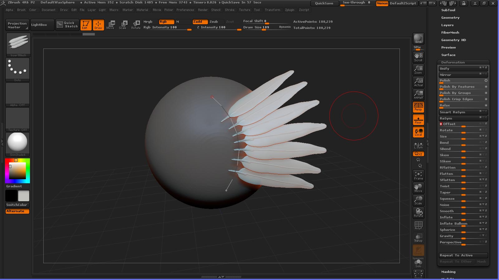
On the feathers, your suggestion would work if the feathers stuck out perpendicular to the surface, but I’m trying to get them lying more or less along the surface - the first image shows how they are now, the second how I would like it to be. Maybe I’ll just have to Offset each row after I draw them in.
I was wondering why is it when I set up a multimesh insert brush to be used with a curve it does what you see on the right? Yet when I take the exact same profile mesh and turn it into it’s own brush all by itself it works just fine? I set up each mesh exactly the same before I turn it into a multimesh insert as the one by it self. For example the picture below. The one on the right is part of a multimesh insert and the one on the left is it’s own brush. Both are from the same set of geometry but the only difference is one is it’s own brush and the other is part of a multimesh set.

Michael,
Thanks for putting all of these videos out there. They are really helping me get started.
I haven’t seen all of your videos yet. I am wondering if one of your videos explains how to navigate back and forth from sub-tools to project. Once I get into a sub-tool I don’t know how to get back to the project.
Michael, Great tutorials, these have helped me a lot.
Anyone,
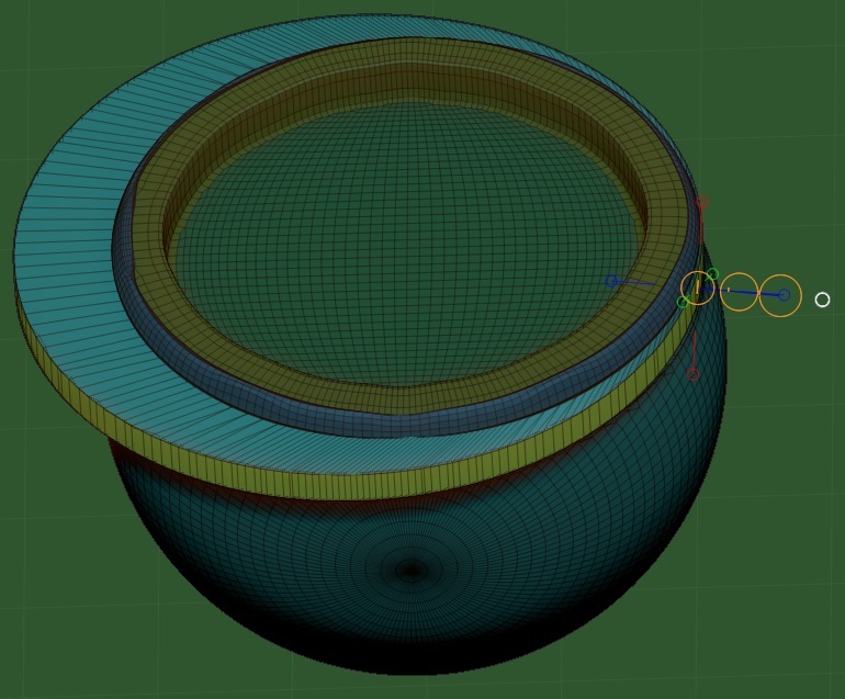
I am working through Michael’s first Transform video and can’t Inflate the ring using the W-Transform feature. The image below shows the problem. I attache the transform brush to the ring polygroup, I pull on the inner red circle of the outer pull handle. The ring inflates but not symmetrically. It inflates away from the brush attachment point. I have tried all ctrl, shift, alt, left and right mouse button, and stylus picks. I can get different effects but I can not get a symmetrical from center inflation.
What am I doing wrong?
Thanks for the help
W is move. R is rotate and S is scale. Try masking the part you don’t want to inflate and use the Deformation Inflate feature?
Hey Doug thanks for the tip. That worked but seems to be a work around to the instructions given in MPs tutorial. In Part 1 of the Transpose videos, within the Digital Sculpting section of the Home Room, MP shows how to Inflate by isolating an edge loop, selecting it with the move brush (W), and then pulling out on the brushes outer red circle. In the video what he does with the transpose tool works just like what you are suggesting with the Deformation/Inflate slider.
I’ll use the work around until I find the solution to this problem. Thanks.
Anybody else seen this?
Watch the status bar while you are on various parts of the transpose line. All dots are not created equal. 
That was the solution!
Watching the status bare was a great tip. I had never noticed that before. I’ve looked for it but never seen it. Probably because in other CAD packages you declare what you are going to do before you do it and then get an instruction. In ZB all you do is select what you are going to affect.
The odd thing is now that I can do this, it isn’t working on a second inflate. On the second inflate the diameter gets larger but so does the face height. It is like the horizontal face is un-masked too. I wonder if this is be cause my edge loops are so close to the corner?
Peter
When I try to unify the skin on a Cube3D, Under Unified Skin I set the Resolution to 16 and Smooth to 0. The Unified skin created has some inverted rows. I have tried adjusting the setting but any Smooth value greater than 0 creates a rounded corner cube, with no inverted edges. Any suggestions on why this is happening?
UPDATE: I restarted ZB and it works now. Ugh.

Just upgraded to 4R6 P2 after a 2 years hiatus from ZBrush and went through a 2 day marathon of most of the on-line tutorials on both Vimeo & YouTube and found yours were very informative. However there’s still a barrier that I encountered the last time I worked with ZBrush that discouraged me. I came to ZBrush with a digital paint mindset via Photoshop & Motion5 and a close CG-pro friend of mine has been my diehard advocate to get into ZBrush because of it’s abilities as a illustrator’s paint program and i wantedto see how my skills as an illustrator would contributor to my 3D digital modeling.
My project 2 years ago was using the SimpleBrush tool to execute some freehand digital calligraphy logos in cast metal liquid bronze ( MatCap01 ) that I was very pleased with , but then I became frustrated with hwat i had created in that I could not discover why I could not convert what appeared to be 3D liquid metal calligraphic forms into an editable 3D mesh ( I now realize this was before Dynamesh which I understand was only just released 6/2013 ). Obviously I’m missing something here , but I can not discover a published satisfactory answer to this question.
So I offer it now to you. Can I produce editable 3D Dynamesh using naturally freehand drawn Illustrated Lettering calligraphy curves using Freehand brushes or do I have to craft Illustrated Lettering out of ZBrush clay? Please forgive for my ignorance, but I have looked for an answer to how I would be able to do this amidst most of what’s already out there on ZBRush and am left still scratching my head.
Help me, ZObi-Wan:(
Try looking at this series. If I understand you correctly this set of videos could help you achieve what you’re after.

Drew a letter and made it 3D, if that’s what you mean then look at those videos.
Yeah , this is where I’m seeking to go and suspected that researching the masking brush feature was a way to go. I have been going through this tutorial as of this writing in order to understand this specific technique within ZBrush. The specific approach comes across a bit counter-inuitive to me with regards to the specific hotkey operations, but then I still have to master ZBrush’s UI
so I 'm hoping working familiarity will heal that sense of counter-inuitiveness.
I just have to get used to how ZBrush operates.I do appreciate not being forced to achieve this procedure using Z-spheres. I’m getting it that what has to be done to make freehand-brushed lettering 3D editable requires freehand-brushing the lettering onto a properly subdivided mesh in order to capture the finer details of a calligraphy brush curve the way I can achieve with a Simple brush. I have noticed the level of detail allowed in the brush paths that the various PenToll footprints make. I’m talking about is to be able to achieve freehand calligraphy on the level of a script font which I can do.
What I mean by intuitive would be being able use the simple brush to freehand brush a letter that would generate the usual series of close-packed ovals that comprise any brush path, as in Photoshop or Motion , and have ZBrush generate an editable 3D mesh generated out of each in-between oval profile along that brushpath. What I’m learning is that that’s not how ZBrush operates.
Anyway, what has emerged for me in all of these suggestions is discovering how far I can push the proper use of the masking brush tool as my calligraphy brush on an already created 3D mesh plane and then using the resulting mask of the brush path to define an editable 3D mesh letter based upon that resulting freehand-brushed mask. The issue becomes the amount of edge detail ( as in sans-jaggies ) one can achieve to preserve the accuracy of the freehand calligraphy brush path made 3D by being able to convert that mask brush path into a 3D mesh. Sorry if my explanations appear a bit wordy ( I notice that my ability to upload image’s of graphic examples of the level of calligraphy I am talking about does not have its permission code turned on and I’ve no instructions how to get that forum feature turned on so I can’t ) , but this is how I best describe it and the responses have been very helpful indeed.
Quick screen shot, I know it’s not exactly calligraphy but you can use anything really. I just grabbed an alphabet off the internet and made this Z 3D with masking in less than 2 minutes. Unless you’re doing something absolutely insane you should be able to take any calligraphy you do and make it into a 3d tool. And even then the most insane is achievable if you learn your tool set. Hope it helps. By the way I used light box to paint it on to a plane and masked by intensity and poly grouped that mask then hid the rest of the plane and then deleted hidden then used panel loops. Like I said less than two minutes. Good luck in your explorations.
[QUOTE=mrmedellin; I know it’s not exactly calligraphy but you can use anything really. I just grabbed an alphabet off the internet and made this Z 3D with masking …you should be able to take any calligraphy you do and make it into a 3d tool. …Hope it helps. By the way I used light box to paint it on to a plane and masked by intensity and poly grouped that mask then hid the rest of the plane and then deleted hidden then used panel loops. Like I said less than two minutes. Good luck in your explorations.
I do appreciate your feedback ,Mr.Medellin, and only just this morning fell upon a ZBrush tutorial on YouTube that reinforces your solution. It’s entitled Creating lace Panel for Insert Mesh Brush ***9654; ZBrush - Creating Lace Panel for Insert Mesh Brush - YouTube which demonstrated to me that one could use a brushpath image with delicately detailed lace patterns and translate them into rather detailed & ,more important , fully editable 3D meshes. Only problem was ,and it’s unignorable , that the tutorial author offers no commentary whatsoever in describing her process choices and the resolution loses substantial clarity when full-screen so one can not read the bloody UI text thus you have to already know the UI like the back of your hand to fully understand her precise procedure . This is why I love this forum because under what words in the index would one query in order to read about this procedure in the manual’s index or the Get Started Guide? Trust me I looked. I’ve found that being pointed toward well-executed tutorials are the way ( BTW: Thank you Mr. Pavlovich). That said this eye-opening process was given further reinforcement by the Make Jewelry Ring Using Alpha ZBrush which informs me that I can just craft whatever detailed calligraphy I chose using Photoshop’s fully adjustable calligraphy brush to create an alpha of my freehand illustrated lettering and import it within ZBrush and convert that into a fully editable 3D mesh. This solution works for me as far as allowing me my thoroughly familiar intuitive flow of brush execution. I can use Photoshop’s fully adjustable calligraphy paint brush , like I’ve always done ( I guess my mistaken approach was in thinking that I could do that within ZBrush , and just export it into ZBrush as an alpha brush print and project it upon a 3D mesh plane and adjust its desired thicknesses & materials accordingly. Sounds like the most intuitively natural solution to me. Am gonna experiment with this approach from this moment forward thru nightfall.
I checked out that video and it looks like she did what I had described with polypaint and masking with maybe a little more time in adjusting the options for masking and spotlight along with the panel loops features.
She states a simple explanation for what she did: “A little Nosferatu design in a lace panel created for an Insert Mesh Brush. Spotlight texture applied to plane, then masked by intensity. Panel Loops created with unwanted areas then deleted out. Alpha used to create bumpy texture. Inflate brush used to simulate knots on larger areas. Color and Cavity Mask painting applied for texture. Zremesher (not shown) was then used to cut the size in half before making the Insert Mesh brush in a more practical form.”
Which happens to be exactly what I did for the Z I showed you minus the inflate brush and textures. And then the whole business about insert mesh creation is just so she can insert it later into a piece or whatever she wants it for. But yeah do all the videos I told you about and the spotlight videos in the class room and even the IMM brush tutorials and you’ll be well on your way to getting what you want. Good luck.
EDIT: I forgot to mention you can polygroup by mask using ctrl+w. Just a tip.
