ZBrushCentral

WrapMode issues - cannot avoid getting edge seams

thanks for the informative thread, guys. :slight_smile:

I did a quick test of your technique, TVeyes, and unfortunately, I’m coming
up with seams on the exported Zmapper-normalmapped texture as well.

I even tried the Photoshop trick of exporting at a larger resolution, cropping
canvas a couple of pixels, then re-sizing the image to proper size (1024 in my case)
and I still get them:

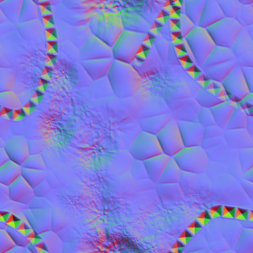
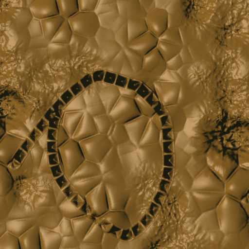
First pic is the normal map (resized for posting here), second is a preview of
the Photoshop-edited normal map in Crazybump, which is handy for showing if seams are present.

Might be close enough for some things, but the seam could be quite
troublesome for others… :frowning:

WailingMonkey

WailingMonkey: Unfortunately using ZMapper to create the normal map I also get seams. I ended up positioning and resizing the tool to fit the exact dimensions of the canvas and dropped the tool. I then applied a Normal shader material to the pixols and exported that. No seams as far as I could tell but I will have to try it again when I get home to make sure.

Note, the NormalRGB material (material #101) that comes with ZBrush crashes the program as soon as it is selected so I had to create my own.

After another test I found seams in the pixol based normal map, but that is due to an old render artifact in ZBrush that occurs along the top and left sides of the canvas. This kind of seam can be completely removed using an old script I wrote. The script is currently under maintenance, so to say, but if either of you have a burning need for it right here and now then send me a PM.

The first picture is the normal map generated from ZBrush and the second is the map applied in Modo. I might be blind but I cannot find any seams.

[attach=78122]WrapModeNormals.jpg[/attach][[attach=78123]WrapModeRendered.jpg[/attach]](javascript:zb_insimg(ā€˜78123’,ā€˜WrapModeRendered.jpg’,1,0))

Attachments

WrapModeNormals.jpg

WrapModeRendered.jpg

hmm…that’s looking pretty acceptable, TVeyes. Was this based off the same
technique you’ve described above, or something additional you tried (or did
you do the plane-rescaled-to-fill-canvas-with-custom-normal-map instead of
taking the actual created normal texture from zmapper). If you take your
image into Photoshop and set up guide lines at 256V and 256H for reference,
you’ll see a very slight repeat (maybe enhanced by .jpeg artifacting) when
zoomed up, but again, I don’t think it’s noticable unless you’re REALLY looking
for it.

I’d sure be ready to try your script whenever it’s out of it’s ā€˜maintenance’
stage :wink: , but nothing burning at this point for me. :slight_smile:

Thanks for putting some more testing into it! This could be a pretty handy
technique if the seamlessness can be dailed in.

WailingMonkey

Hi WailingMonkey, The normal map on the left was not offset so unless you offset the texture yourself you must be viewing jpeg artifacts. I am 99 % sure the method I used results in 0 seams (except if you use the smooth brush on the geometry edges).

Unfortunately the zscript recording I was annotating does not playback as expected. So I will post some form of step-by-step tomorrow together with the script.

Are you aware of the alternative method of creating your details through pixols instead of geometry when aiming to generate normal maps? In any case with this method you can use both traditional 3d scultping coupled with 2.5d drawing before generating your normal, color and or displacement map. For planar geometry of course.

Howdy TVeyes,

I offset in Photoshop by 256 pixels, but I think I’m looking too hard
for the seams…I think you are correct that there are none (no one
should be viewing it at 500% zoomed-in). :slight_smile:

If you are talking about using the tilde (~) key to manipulate the canvas
as you place down pixols, yes, I’m familiar with that method. It is a bit
cumbersome though, in that you have to increase your document size
by something like 10 pixels (1034X1034), render at ā€˜best’, export document,
take into Photoshop, resize (crop) canvas by 1 pixel all around, then
resize the image to 1024X1024…and it doesn’t guarantee seamlessness, but
just gets it ā€˜close’.

I’d love to have a process in the arsenal that was bombproof against seams. :wink:

WailingMonkey

Aurick? Is this a bug?

This workflow looks solid, the no smooth brush at the edges is a bit restrictive, but I guess if I really need something smooth on the edge I can drop the tool on the canvas and use the blur brush. Definitely less restrictive than not being able to use a load of brushes and no alphas. :slight_smile:

I’ve been using the NormalRGB material, and sometimes I get these odd white pixel artifacts on flat surfaces when I render on best, like this:

white_spots.jpg

have you guys seen this at all?

littlelostalien: I cannot load the NormalRGB material into ZBrush 3.1 without crashing the program. But those white spots definitely did not appear during best renders in ZBrush 2.

I am sure you are aware of this but in any case. If you are going to use the smooth brush on the canvas then remember to offset the canvas (under the Layers palette) before smoothing the edge pixols.

WailingMonkey: I will post the workflow and the script tonight. Sorry for the delay, I went and got myself busy.

In cases with open edged geometry ZMapper will unfortunately output a normal map that shows a slight seam when the normal map is tiled. This is not a problem for the majority of models that pass through ZMapper but when we try to create tileable normal maps much like we would create them on the ZBrush canvas, this becomes a problem. Fortunately you can take advantage of both the 3D brushes and the 2.5D brushes when creating normal maps from a flat and square piece of geometry and still end with a tileable normal map without seams.

Preparation and sculpting. 1) Select the Plane3D tool and turn it into a polymesh with Tool > Make Polymesh3D. Alternatively import your own flat and square geometry. 2) Disable Tool > Geometry > Smt (Subdivision smoothing) and subdivide the tool as many times as needed.Disabling subdivison smoothing allows us to keep the original boundaries which is a must for later on. Keep in mind the normal map output size when you subdivide as we will be converting the tool to pixols. Any smoothing to the final output will be achieved mainly through the Zoom > AAhalf view mode. A polygon to pixol ratio of 1 to 2 is about as low as you want to go without utilising other means of smoothing. 3) Press Tool > Layer > New to create one or more layers. All sculpting must be made with an active layer selected. 4) Draw the polymesh tool on the canvas, enter Tranform > Edit mode and select your edit mode brush. 5) Set Brush > WrapMode to 1 or higher and start sculpting.A value of 1 allows the stroke to continue from one border of the geometry to the opposite border. Higher values simulate multiple strokes continuing from one border to the other. The WrapMode setting is a brush setting and so needs to be set for each brush you use. * Do not use the Smooth brush, with or without WrapMode, near the borders of the geometry. Using the Smooth brush there will result in seams. It is better to apply smoothing during the last stages. 6) Save the polymesh Tool.This step may seem superfluous but the following steps cannot be repeated on the same tool without causing unwanted sideeffects. Use this backup each time you want to continue to the next section. Removing seams from the polymesh When you are finished sculpting we need to realign the borders of the polymesh as they become offset along the XY axis during sculpting. Unless corrected there will be seams in the final output. 1) Turn off all layers by clicking the eye icon of each layer.

2) At the highest subdivision level store a morph target with Tool > Morph Target > StoreMT.
3) Turn on all layers by clicking the eye icon of each layer.
4) Disable the Z axis on the Tool > Morph Target > Morph slider and apply a morph at 100.* Optionally apply a mask to the inner areas of the polymesh to retain any extreme XY axis sculpting. But remember, this workflow is for normal maps and so extreme sculpting across the X and Y axis does not yield better results. You are always going to capture the normal map from an orthogonal front view along the Z axis. Of course, it is easier to create some effects with some brushes that cause larger XY axis changes. In those cases or when you need extreme precision use Tool > Geometry > Reproject Higher Subdiv before step 1. This should be applied to each Tool layer at the lowest subdivision level.
5) Save the Tool under a new filename as repeating steps 1-4 on the same tool will result in unwanted morphing.

Capturing the Normal Map Dropping a tool to the canvas results in a what you see is what you get when creating normal maps for flat geometry. This means you should resize the canvas to your normal map ouput size, optionally doubling the size to allow Zoom > AAhalf to smooth the output. 1) Resize the canvas to accomodate the aspect ratio of your geometry. For the Plane3D polymesh tool turn off Document > Pro, set Document > Width and Height to a multiple of 2, for example 1024 x 1024. Press Document > Resize.Geometry with a different aspect ratio than 1:1 can also be dropped as long as you resize the canvas accordingly. 2) Centering the polymesh tool currently requires a little mathematical skill. Hold shift, draw the tool on the canvas and enter Transform > Move mode which will bring up the transform gyro. Adjust the X and Y values of the Transform > Info sliders to half the current canvas dimensions. Enter Transform > Scale mode and enter Transform > Info XY values of half the current canvas dimensions. Now drop the tool by exiting any active transform mode.* Although you can apply various Tool > Display Properties to smooth the geometry before dropping to the canvas you should avoid it as it will contract the edges of the geometry, which will cause seams in the normal map. Entering Transform > Info values can feel a little fidgety in 3.1. But if you remember pressing TAB moves to the next entry field, ENTER applies the value and ESC removes the entry field focus you should be fine. 3) Load the NormalRGB material to apply it to the currently visible pixols.If your polymesh Tool contained multiple material references the easiest way to fill them all is to select the SimpleBrush, enable Draw > M and disable Draw > ZAdd and drag until you fill the canvas. * Currently I cannot load or apply the NormalRGB material that comes with ZBrush 3.1 without crashing the program. If you experience the same then use the NormalRGB_TVeyes material below. 4) Disable Render > Shadows and any other render options. Enable Render > Best Render and press Document > Export. The above steps may seem complicated but they are just fleshed out a little. If you know your way around ZBrush you will have arrived at this point in the text much earlier. + 10 Z points to you ;) EDIT : The normal map material below can be captured using the above steps. But certain materials that use certain material modifiers (Cavity shading for example) need extra steps to capture a map without seams. Capturing other maps. Depending on the materials used and render options it is necessary to perform additional steps when capturing a seamless color, bump or specular map from the canvas. Determining exactly which materials cause seams is difficult. Instead it is easier to always use these steps when capturing those types of maps as it will ensure a seamless capture each time. 1) Resize the canvas to accomodate the aspect ratio of your geometry. For the Plane3D polymesh tool turn off Document > Pro, set Document > Width and Height to a multiple of 2, for example 1024 x 1024. Press Document > Resize. 2) Hold shift, draw the tool on the canvas and enter Transform > Move mode which will bring up the transform gyro. Adjust the X and Y values of the Transform > Info sliders to half the current canvas dimensions. Enter Transform > Scale mode and enter Transform > Info XY values of half the current canvas dimensions. Now drop the tool by exiting any active transform mode. 3) Enable Draw > MRGB and ZAdd. This is needed when using the script in the next step and when baking the document in the step after that. 4) Load the TTR_rev_a.zsc script, press ZPlugin > Misc Utilities > TTR WIP and press Add in the script interface that appears. This adds 32 pixols to each side of the canvas. 5) Enable Render > Best Render and press Layer > Bake with a bake value of 100 (the default). Set render mode to Render > Preview. 6) Remove the canvas area we added in step 4 by pressing ZPlugin > Misc Utilities > TTR WIP and selecting Subtract in the script interface. 7) You can now enable Render > Best Render again and export with Document > Export. Note > The TTR_rev_a zscript needs to be loaded once per ZBrush session. It should not be placed in the ZBrush3/ZStartup/ZPlugs folder. Instead unzip it to some familiar place and load it from there.

Sorry about the delay Wailingmonkey, and perhaps also excuse the formatting. This forum does not like editing post with indents. I tried but it just makes it worse as you can see.(Edit> think I fixed it after edit # 17)

The TTR script (Tileable Texture Rendering) is an old script that has a more advanced version. At some point in time, when pigs fly and all that, I will post it.

Edit > Littlelostalien > I forgot to mention I also get the same white speckles using my material from below. The solution so far is to turn off Preferences > Performance > MultiRender when rendering normal maps or other documents with materials that create these darned speckles.

Wow. That’s quite an effort. Thank you for posting and sharing this, TVeyes!

I didn’t know you had that canvas resizer/padder since 2004?!? (I musta
skipped right over it).

Oddly, after trying the process I’m left with 2 pixels on top (of a
1024X1024 canvas) and 1 pixel on bottom that get a grey border, thus
breaking the seamlessness. I’ve set preview shadow to ā€˜0’ intensity, but
it doesn’t have an effect (I’m guessing it’s occuring on the ā€˜Best’ render
and baking them in?). If I go into Photoshop and crop the canvas, then
resize to 1024, I lose that 3 pixel lines of data so whilst the repeat is
seamless on the horizontal, it’s missing info (and breaking seamlessness)
on the vertical.

I’ll mess around a bit more and see if it’s just user error on my part.

Thanks again for taking the time and effor to document this! It’s much
appreciated by me, and it’d probably be a nice addition to the tutorials
category of the site. :wink:

Now all I’ve gotta do is figure where I’ve borked it. :slight_smile:

Kind regards.

WailingMonkey

EDIT That’s bizarre…if I do an MRGBZGrabber on it, I get only a grab of
1024X1021 pixels on the exported .PSD (not a document export, even tho
it’s still at 1024X1024 pixels). Something is amiss here…

WailingMonkey, don’t worry, it was me who borked it :slight_smile: The script is not needed when capturing normals maps using the zbrush NormalRGB material or my material below. As long as you enable best render before exporting you get rid of the the lines at the top and at the bottom. For other materials and render options I have added a separate set of steps. Sorry about the confusion, it has been awhile since I thought about this.

Please see my previous post for the revised and final steps.

sweet! thanks, TVeyes…got 'er working now. :slight_smile:

I appreciate you taking the time to lay out the workflow.
You’ve given me another tool for the arsenal. :wink:

Kind regards.

WailingMonkey

TVEyes - thanks for all this information and the workflow! That is great.

littlelostalien - the problem you are describing could come from sculpting the edges of the 3d plane while you have it tilted. There are a couple of solutions to that.

First, have the plane perpendicular to z axis of the canvas when sculpting the edges.

Second, turn on picker: once ori and use that when sculpting the edges. Keep in mind each brush stores this setting so you have to change it for each brush you use.

I hope this helps. :slight_smile:

ryan

Cool, speckles are gone :smiley:

Hmmm… well that works when your brush strokes are on the flat plane… but as soon as you work on top of somewhere you’ve already sculpted then it doesn’t help as it won’t be selecting a z- axis orientation anymore.

Svengali emailed me a rather clever approach to creating normal maps without seams, which allows the use of both the edit mode Smooth Brush and ZMapper.

The idea is simply to set Brush > Wrapmode to 2 which simulates the effect of 4 brushes, create the normal map and crop it to 1/4 the size

The only real drawbacks of this approach are the increased amount of polygons needed to create the required details and the maximum ZMapper output size, both 1/4 of your polygon/pixel budget.

Placing details at specific locations can be done by using visual aids such as materials or polygroupings but singular strokes that overlap the edges are not possible.

For many output sizes and tileable normal map designs I would imagine this method is perfect.

Thanks Svengali :+1:

Thanks TVeyes (and Svengali!), my coworkers and I have been using this method for the past few weeks and it works really well! :smiley: There’s the added bonus that you get a preview of what your texture looks like tiled.

P.S. Does anyone happen to know if there’s a way to set the default wrapmode for all brushes to be ā€œ2ā€ instead of ā€œ0ā€?

There are a couple of ways to set the brush settings but not on a global/automated basis as you request.

Simply saving a brush preset to Zstartup/BrushPresets will load that brush upon startup. So instead of selecting the Stich3 brush you select the Stitch3Wrap brush you created.

A script could select a brush for you and set various brush settings but would require you to use the script buttons to select brushes instead of using the brush icon. Another variation would have the script select each brush one by one and set various brush settings.

And finally you could record a macro that sets one or more brush settings and assign a hotkey to it. This still requires you run the macro after each brush change.

They are probably all options you are aware of but that is all I can think of.

I reckon this might be a bug, I’ve started a thread in the questions forum about it before I knew of this thread (I did search, just didnt find this one though)

Thanks for all the ideas for workarounds! Let’s hope it can be remedied at some point in the future. :slight_smile:

Hello Zbrushers,

I am having problems creating repeating patterns like others in this thread. I am trying to create patterns by starting my design using the simple brush directly on the canvas, using the tilde key to move around and then exporting. The purpose of these repeating patterns is to create fabric prints. Whenever I export the image there is a black border around the design making it useless as a repeating pattern.

I have tried using the suggestions laid out by TVeyes in the section ā€œCapturing other mapsā€ to no avail. When I try to do a best render after using his plugin to initially add 32 pixols to each side of the canvas, zbrush 4r4 crashes every time. I am able to avoid zbrush crashing during the best render if I start directly using the SimpleBrush onto the canvas rather than drawing out a Plane3D as TVeyes suggests, but when I finish all of his steps I end up with a semi transparent border around the exported image rather than the black border I had previously - which is marginally better but still not useful as the pattern is not seamless.

Is there a new method of fixing this problem in 4r4? I am really pulling my hair out over solutions to this problem.

Any suggestions would be great.