rv_el - ZMapper’s projection option does not work with cavity maps at this time only normal maps. 
Ryan
rv_el - ZMapper’s projection option does not work with cavity maps at this time only normal maps.
Ryan
Let me know if this sounds crazy, but It might be worth a try.
Can i create a Cavity Map the same exact way the tutorial video shows, only using some sort of auto unwrap feature.
Then i save out that cavity map as a bitmap, and i also export out the low poly OBJ with its new UV layout (matching the generated cavity bitmap)
Then i import the OBJ into MAX and apply the Cavity Map to it.
Then on the (very similar) model with my own UV set on it… I run Render To Texture and Render a complete/diffuse type map referencing the model from Zbrush… thus baking the cavity information from the Zbrush one over to my new UV set.
???
If this is possible, what would the steps be. Mostly i’d need to know how to generate the cavity map for a new auto uv set in Zbrush.
Thank you
Hey guys … I’ve run into a real WEIRD problem …
I’ve recently installed the ZMapper plugin in the correct directory … but ZBrush can’t seem to find it …
I’ve tried manually loading it as well …
Here’s a screengrab :

When I click on the icon, I get this message :
ZScript Note : The Zmapper plug-in could not be found
Anybody else get this issue?
Strange …
Is there an environment variables-type text file I can manually edit to show ZBrush where the plug-in is?
I’m running ZBrush 2.0 with ZMapper Rev D
Thanks for your help guys.
Hi Ryan,
Thanks for posting this , I used it last night and my normal maps using maya software renderer are very close to the displacement maps via mental ray. I did find that I needed to flip the green chanel to get a clearer picture and increase the filter in maya to smooth out some seams but it looks good.
Cheers
Never before have I seen a normal map to be comparable to a displacement map, except perhaps for smaller details.
Never before have I seen a normal map to be comparable to a displacement map, except perhaps for smaller details.
Depends on how close you get to the object. Check out my workhere for an example of displacement map vs. a normal map.
Wow very cool. But thats using a displacement map isn’t it? I didn’t look at the whole thread, my university internet data cap is very low :lol: So I couldn’t tell which was normal mapped or displaced (I stopped when pic was half loaded )
I’ve heard about using both a normal map for high frequency details and displacement map for medium frequency details, but wouldn’t it be better to use displacement map for both anyway? Its not like its less detailed…
The second picture in the post is the one I was referring to.[font="]
here
sometimes it is hard to get high frequency details with displacement maps, and it is often mcuh easier to use normal or bump maps for high frequency details
and sometimes (like with games) you cant use displacement
Hi, I have another problem now, when I import a model from max, always show up that UV problem, how can I fix that? And my normal maps always comes with many errors, why?
Thanx.
I have the same problem.
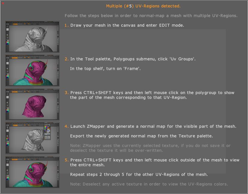
I make low poly model in max8, create UV map, export .obj, import in zbrush, convert it to polymesh, subdiv it, add detail, go to lowest subdiv lvl and when i want to start zmapper it says that multiple uv regions have been detected and bla, bla, bla… suggested steps don’t work and i don’t have mupltiple uv regions, it’s all in one tile. What is the problem?
Plz help!
luisaum_gma - Can you please post specific issues you are having with your UV layout and/ or the problems with the normal maps? I can not offer any help with the information you provided. Sceen shots are extemely helpful as well.
NenadB - ZMapper is telling you that you have UVs outside the 0-1 area. It could be that you have some UVs lying directly on the border. These could be seen as part of other UV regions. Can you post an image of your UV layout? Also, what was the result of the steps that it asked you to take? Please be specific. I know there is an urge to post that it just doesn’t work but there is nothing that I can do with that answer. 
Best,
Ryan
Thanx for reply Ryan,
as i said, uvw map is in one tile, here is a pic of uvw map and screen that pop up when trying to start ZMapper:
NenadB - unfortunately I can’t tell much from the image of your UVs. Is there a border area or line? My main question is if you select one of the verticies is it possible that it is placed at the border of the 0 to 1 region?
Also, check out the ZPipeline guide for Max 8. Here is something that may help:
"Once you have fixed overlapping faces and welded the verts, you should apply a Reset Xform and collapse the stack. This is a clean up measure that will ensure that the geometry transfers cleanly into ZBrush. When collapsing the stack choose Editable Poly. The Poly object is the best choice for compatibility between 3ds Max and Zbrush. " section 2.1
Ryan
Ryan - image above is rendered UVW template so edge of image is edge of region. Now, Max doesn’t show overlapping and all vertices are in 01 region but still UV map isn’t exported properly since UV Check in ZBrush show overlapping. I’ve tried Reset XForm (altough i don’t know what does that do :rolleyes:) but same thing happens. I’m sure i’m doing something wrong in Max i just can’t see what…
Ryan - i’ve FINALLY found what was wrong. My UVW map was in channel 3, but i also had UVW map in channel 1 (didn’t know that btw) and that map was messed up. Somehow max always exported map in ch.1 and not in ch.3. So, i cleared bad one and all worked fine in ZBrush…i’m soooo happy…:lol:
Thanks again for help Ryan!.
someone asked this earlier, thought I’d ask again; anyone get their maps to render cleanly in maya software?
frustrating that they look perfect with the ‘high quality’ viewport preview, but fall apart in the software render. Isn’t it meant to be the other way around? :rolleyes:
Just as a sanity check, here’s my workflow:
-generate normal map using maya 7 preset, 1024x1024 map (although the default settings worked fine once the map was flipped)
-in maya, have file -> bump2d with ‘tanget normal space’ -> blinn
-polysmooth cage once, render
I’ll upload a screenshot tomorrow, but basically we’re getting black facets where the normal map hits large curvature changes, like warts. The map itself looks smooth, and the high quality viewport preview looks fine (fantastic in fact), but maya software render refuses to play nice.
I’ve tried exporting 4k maps, using the other maya presets, generating based off level 1 subdiv vs level 0, etc etc… minor improvements with each change, but nothing we could use in production.
Any ideas?
Cheers,
-matt
I’m having that UV problem. How can I unify the UVW map on zBrush? I need to do that on max? Thanks.
Bit of help from the highend3d mailing list pointed me to this:
http://www.pixero.com/downloads_maya.html
http://www.pixero.com/files/JSNormalMapper.zip
I thought Jan only wrote mentalray shaders, but this is for the internal maya software renderer. Works a treat!
Hope this helps someone…
Cheers,
-matt
NenadB - cool. glad you sorted it out.
mestela - the maya presets are designed for the viewport, not software render. Also, they are designed for when you hook up the map.outcolor to the material.normalcamera. Last time I looked the bump node takes the alpha as an input which would preclude it from listening to the rgb values of the normal map which is really what a normal map is about. Otherwise, Maya is simply converting a normal map to a bump map and then using that.
Best,
Ryan
Hi guys,
I’ve been reading this thread hoping to see some other ppl with the same problem as mine.
My workflow:
Low poly model in 3ds max
import into zbrush
subdivided 4 times
go to first level then zmap…
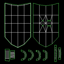
Here is what I get from the UV morph…

Why is only half my ‘UVs’ showing up?
Here’s the original model…

And here’s the resulting normal map

My uv map…
