ZBrushCentral

Five o'clock tea

Ok, Ziggy.

I’ll share my modest experience in wood carving CNC

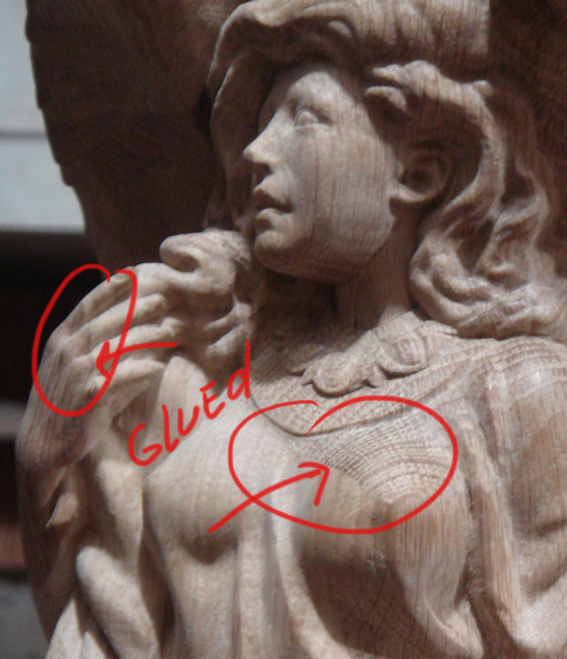
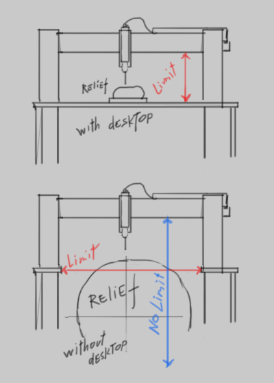
I’ll start with the disadvantages CNC. They have the limitation of motion of the spindle axis Z to the surface on the desktop.
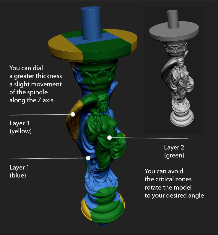
This prevents a large volume dial details.
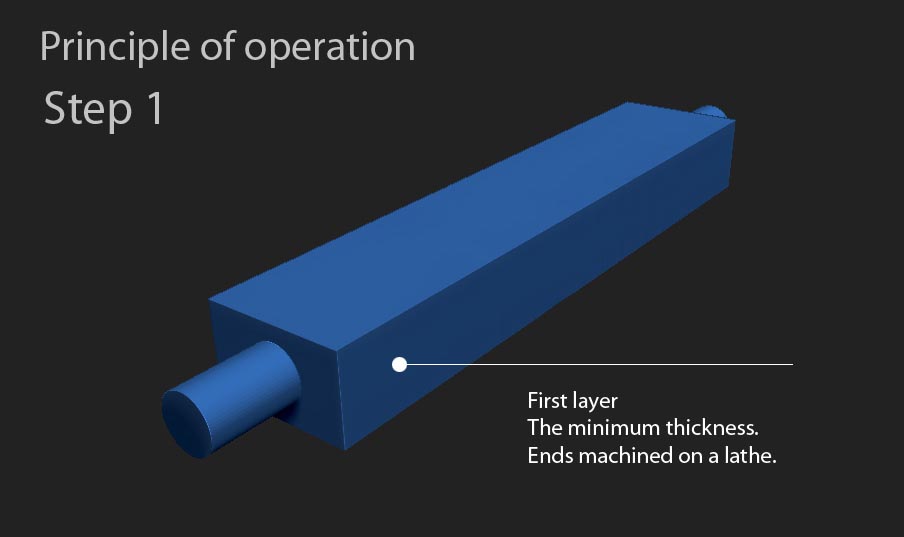
Our solution was so - remove the desktop. It was the right decision and allowed the model to increase the thickness of the width of our machine.
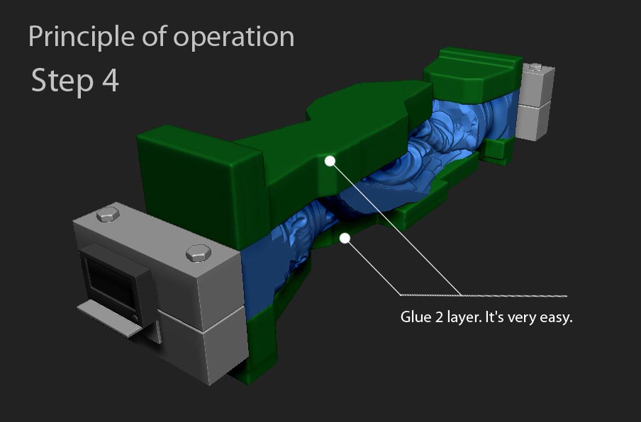
Look at this.

scheme.jpg

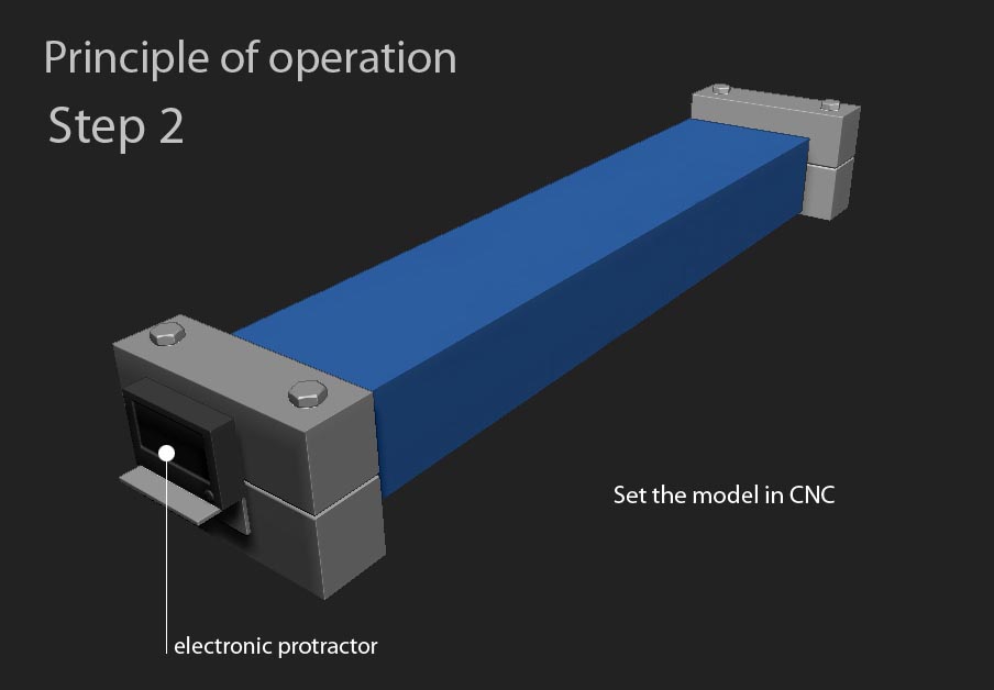
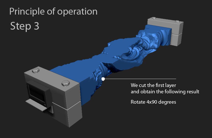
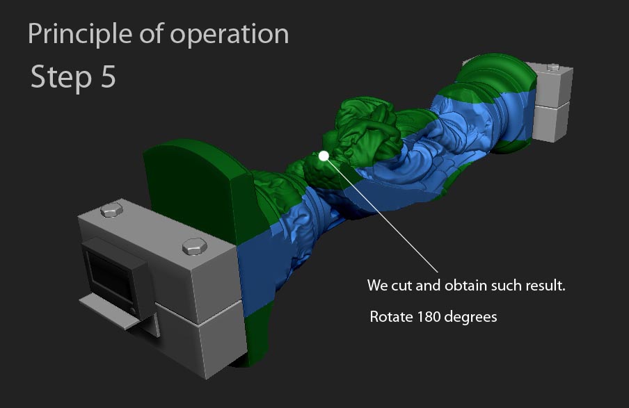
Now you can rotate the model.
raise and lower. For this device can make any turner.

Now I think the basic idea is clear.
Everything is simple.:wink:

…so you’re still limited by the Z axis travel correct?
You’re just giving more room for the stock instead of going above the cutting bed which is where a typical 4th axis would mount to.

…so if you have, for example, 5 inches of travel in Z then you still have that limit but can work with bigger stock is all. It’s a nice approach to cutting bigger stock, have seen others set up this way to cut bigger stock.

  • I have a CNC build in progress and plan on adding a 4th axis down the line as well

…If the spindle travel, for example, 100 mm,
material thickness of 50 mm, quietly cut to 0.
Next, glue the new material thickness of 50 mm to the already carved relief, move the model down to 50 mm, and cut again.
This is repeated the necessary number until there is a desired thickness

Previously tried to cut layers and then these layers are glued together - turned out badly - it is difficult to glue relief
Now the bonding quality and seams virtually invisible - you can define only by the texture of the wood.

example.jpg

wow…okay…that seems like a lot of work with no rotary axis.
So how did you do all sides of it…since you’re just doing slices? You did half of the entire model that way and then flipped it over to do the other half??
There are a lot of concave areas…so i guess it wouldn’t work that way…just curious how you achieved the entire thing like that?
A quick diagram of the slicing you did?? or pictures of the process??
thanks

… and here’s the trick is - we have a rotary axis, but the turn is done manually at any desired angle. For this we use an electronic protractor.
The program prescribes the only place to be processed.

Ok. I will prepare the basic principle of work in pictures.
Just take some time

okay thanks…that makes a little more sense to me…still sounds complicated to get it all setup correctly

This is very interesting and will gladly like to see the new diagrams…

Maybe a video one day?

Ziggy

HI All!

I want to share their experiences

I use Zbrush to create models for carving CNC.

Some time ago we implemented the idea of 3D carving on 3 axis machine CNC.
You can see the working principle.

Step-1.jpgStep-2.jpgStep-3.jpgStep-4.jpgStep-5.jpg

I hope that it is clear and you will enjoy.

Attachments

Finish.jpg

Thank you for the detailed explanation…great job.

Looking at Step 5 i’m still confused how you achieved the under cut details?
So you moved it down, glued on a new layer, cut one pass, rotate 90 and then rotate -90 to get all of the details the rotate 180 and do the other side?

thank you,

Of course!

Rotated 90 degrees and level the surface for the next layer

strange thing to implement this in zbrush, but i can only congratulate your efforts. Great handling of both arts.

Freewaldo, thank you

Very interesting! Thank you for going through the trouble to illustrate the process. Lovely results!

Hybryd75, thank you.

Kruto! Smekalka - ona i v Afrike smekalka!:))

EgorDD, thank you.
Spasibo :wink:

Ignoring the process which is awesome in itself, the models them self are really great.

Slocik, thank you so much!

Brilliant concept and beautiful work